
Centrifugal pump for farmland irrigation

A technology for farmland irrigation and centrifugal pumps, which is applied to pumps, parts of pumping devices for elastic fluids, pump components, etc., which can solve the problems of enhancing the experience of using centrifugal pumps, troublesome operation, and small centrifugal force, and achieve enhanced user experience , avoid time-consuming and labor-intensive effects, and increase the impact

Active Publication Date: 2020-11-20
JINYUE ELECTROMECHANICAL CO LTD
View PDF4 Cites 0 Cited by
  • Summary
  • Abstract
  • Description
  • Claims
  • Application Information

AI Technical Summary

Problems solved by technology

[0003] However, when the centrifugal pumps on the existing market are started, if there is no liquid in the pump or the liquid is not full, there will be air in the pump casing. Because the air density is very low, the centrifugal force generated after rotation is small, so that the impeller center area is formed. The low pressure is not enough to suck the water in the pool into the pump, even if the centrifugal pump is started, the pump cannot be transported, and the pump must be filled with water before starting, which causes inconvenient use and troublesome operation. Centrifugal pump, the centrifugal pump realizes the automatic pumping of the centrifugal pump through the suction unit, thereby avoiding manual irrigation before starting and enhancing the experience of using the centrifugal pump

Method used


Image

  • Centrifugal pump for farmland irrigation
  • Centrifugal pump for farmland irrigation

Examples


Embodiment Construction

[0018] In order to make the technical means, creative features, goals and effects achieved by the present invention easy to understand, the present invention will be further described below in conjunction with specific embodiments.

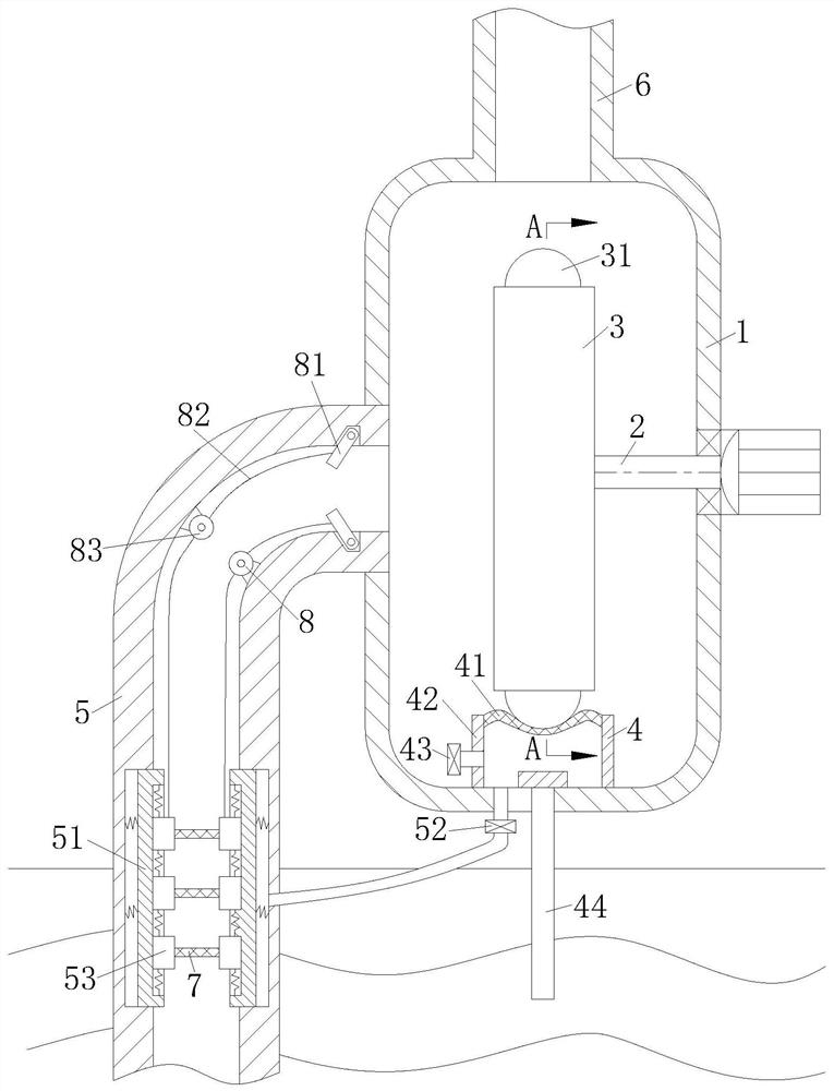
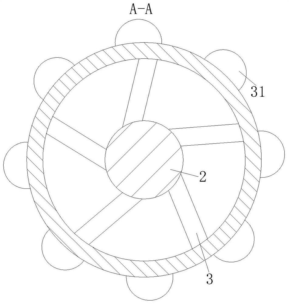
[0019] Such as Figure 1 to Figure 2As shown, a centrifugal pump for farmland irrigation according to the present invention includes a pump body 1, a controller, a rotating shaft 2, a motor, an impeller 3 and a suction unit 4, and a controller is fixedly installed on the outer wall of the pump body 1, One side of the pump body 1 is provided with a water inlet pipe 5, and the top of the pump body 1 is provided with an outlet pipe 6; the controller is used to control the automatic operation of the centrifugal pump; the impeller 3 is installed inside the pump body 1 in rotation, and the outer ring of the impeller 3 is uniform A group of protrusions 31 are laid; the motor is fixedly installed on the side wall of the housing opposite to the water inlet...


PUM


Abstract

The invention belongs to the technical field of fluid pumps, and particularly discloses a centrifugal pump for farmland irrigation. The centrifugal pump for farmland irrigation comprises a pump body,a controller, a rotating shaft, a motor, an impeller, and a pumping unit. A water inlet pipe is arranged on one side of the pump body and an water outlet pipe is arranged on the top of the pump body.The impeller is rotatably installed inside the pump body, and a set of bulges are arranged on the outer ring of the impeller. The motor is fixedly arranged on the side wall of a shell opposite to thewater inlet pipe, and is connected with the impeller through the rotating shaft. The pumping unit is located at the bottom of the pump body, and the pumping unit comprises elastic films, supporting plates, a drainage solenoid valve, and a water suction pipe. The supporting plates are fixedly arranged on the bottom wall of the pump body. The number of the supporting plates is four. The two adjacentsupporting plates are fixedly connected with each other. The top ends of the supporting plates are covered with the elastic films, wherein one of the support plates is provided with a water outlet. By means of the centrifugal pump for farmland irrigation, the automatic pumping of the centrifugal pump through the pumping unit is achieved, so that the manual irrigation before starting is avoided, and the use experience of the centrifugal pump is enhanced.

Description

technical field [0001] The invention belongs to the technical field of fluid pumps, in particular to a centrifugal pump for farmland irrigation. Background technique [0002] The centrifugal clean water pump is referred to as "centrifugal pump", which is a pumping machine that uses the centrifugal motion of water. Centrifugal pump is composed of pump casing, impeller, pump shaft, pump frame and so on. Centrifugal pumps have many advantages such as wide range of performance, stable flow, simple structure, reliable operation and convenient maintenance. Centrifugal pumps have various forms such as vertical, horizontal, single-stage, and multi-stage. Before the centrifugal pump is started, the pump should be filled with water. After starting, the rotating impeller drives the water in the pump to rotate at a high speed. As the pressure decreases, a low-pressure area is formed near the rotating shaft. The pressure in the low-pressure area is much lower than the atmospheric pres...

Claims


Application Information

Patent Timeline
Patent Type & Authority Patents(China)
IPC IPC(8): F04D13/06F04D9/02F04D29/22F04D29/42F04D29/66
CPCF04D9/02F04D13/06F04D29/2261F04D29/4293F04D29/669
Inventor 不公告发明人
Owner JINYUE ELECTROMECHANICAL CO LTD
Learn More