
Drop hammer type dynamic biaxial extension test device

A biaxial stretching and testing device technology, applied in measuring devices, using stable tension/pressure to test the strength of materials, instruments, etc., can solve the increase in device cost and complexity, affecting the accuracy of test results and processing accuracy requirements High and other problems, to achieve the effect of accurate and reliable test data, compact structure and good versatility

Pending Publication Date: 2019-03-01
NINGBO UNIV
View PDF0 Cites 6 Cited by
  • Summary
  • Abstract
  • Description
  • Claims
  • Application Information

AI Technical Summary

Problems solved by technology

[0003] At present, the equipment used for biaxial stretching mainly includes the following types: (1) Through the octahedral device, the upper and lower points provide loading loads, and drive the upper and lower four slashes to drive the cross-shaped specimen in the middle to perform bidirectional tension. Stretching, the device is relatively complicated, and the loaded load changes from time to time, which affects the accuracy of the test results; (2), through the motor loading and stretching in two directions, the stretching arm of the cross-shaped specimen and the screw form a worm mechanism, Driven by a servo motor, the device requires high machining accuracy and is suitable for quasi-static testing; (3) Loaded by hydraulic cylinders, four hydraulic cylinders drive the movement of the stretching arm of the cross-shaped specimen, although the device can be adjusted arbitrarily The load ratio and loading speed of loading and stretching, but it requires high synchronization of equipment, and requires expensive electronic equipment to coordinate operation, which greatly increases the cost and complexity of the device

Method used


Image

  • Drop hammer type dynamic biaxial extension test device
  • Drop hammer type dynamic biaxial extension test device
  • Drop hammer type dynamic biaxial extension test device

Examples


Embodiment Construction

[0019] The present invention will be further described in detail below with reference to the embodiments of the accompanying drawings.

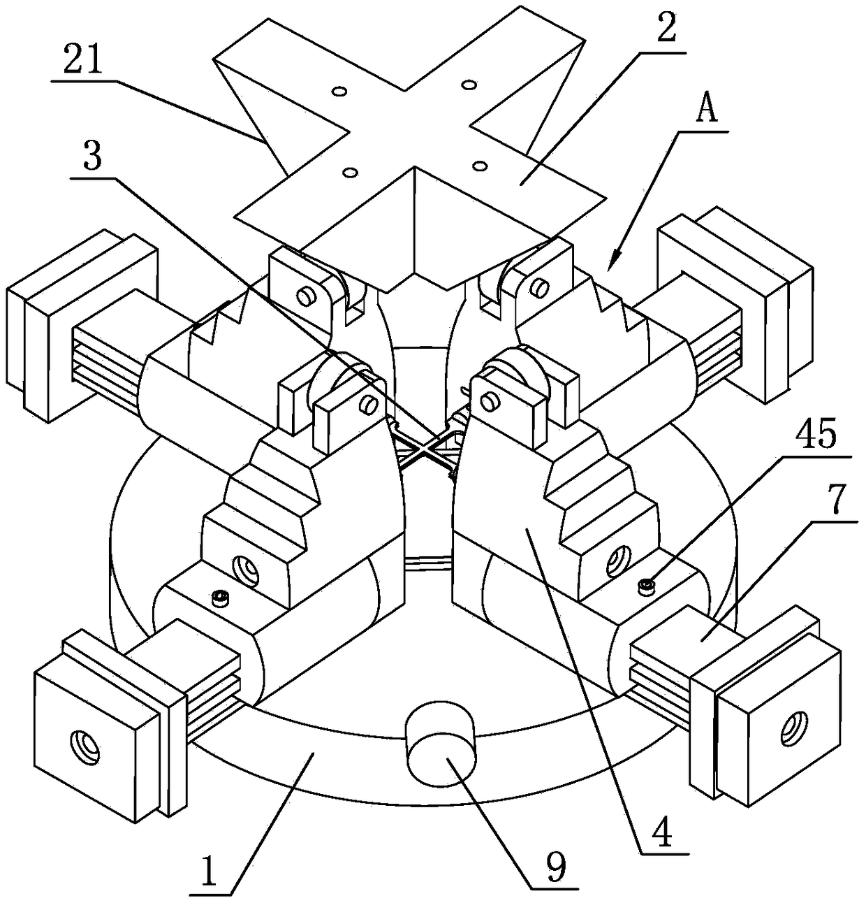
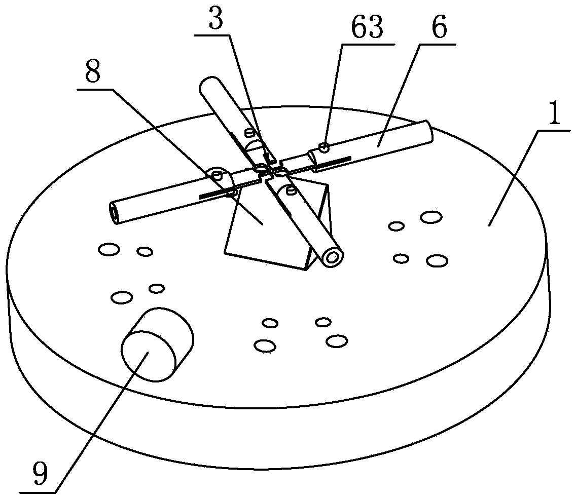
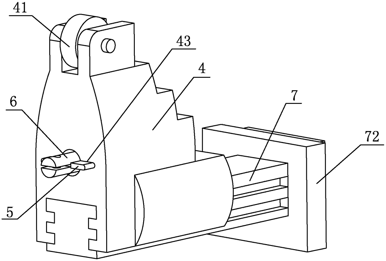
[0020] As shown in the figure, a drop hammer type dynamic biaxial tensile test device includes a chassis 1, a hammer head 2 and four sets of clamping arms 31 for clamping the four tensile arms 31 on the test piece 3 in a one-to-one correspondence. The device A and the clamping device A are arranged opposite to each other, and a sliding device that moves along the length direction of the stretching arm 31 of the test piece 3 is arranged between the clamping device A and the chassis 1. The clamping device A includes a slider 4, The positioning piece 5 and the cylindrical fixture 6, the inner side of the upper end of the slider 4 is hinged with a roller 41, the roller 41 is covered with a rubber ring (not shown in the figure), and the slider 4 is provided with a horizontal fixture installation hole 42, The clamp 6 is arranged in the clamp mounti...


PUM


Abstract

The invention discloses a drop hammer type dynamic biaxial extension test device. The drop hammer type dynamic biaxial extension test device is characterized by comprising a base plate, a hammerhead and four groups of clamping devices, wherein the four groups of clamping devices are separately used for clamping four extension arms on a test piece in a one-to-one correspondence mode, the clamping devices are oppositely arranged in pairs, and a sliding device moves in the length direction of the extension arms of the test piece is arranged between the clamping devices and the base plate. The hammerhead is located right above the test piece, and four planes at the lower end of the hammerhead are inclined planes and directly face the four extension arms of the test piece in a one-to-one correspondence mode. The drop hammer type dynamic biaxial extension test device has the advantages that the four clamping devices are driven to move simultaneously through the hammerhead, four ends of the test piece are loaded simultaneously, the dynamic mechanical type biaxial extension of the test piece is realized, the structure is compact and simple, and the cost is low; and the test piece with different biaxial extension angles and different extension displacement ratios can be loaded by changing an included angle between the two adjacent extension arms on the test piece, changing the positionbetween the two corresponding groups of clamping devices and changing an inclined angle of the lower end surface of the hammerhead, and thus, the loading of the test piece is flexible and varied.

Description

technical field [0001] The invention relates to a device for testing mechanical properties of materials, in particular to a drop-weight type dynamic biaxial tensile test device. Background technique [0002] Stretching is the process of elongating the material or sample on the plane under experimental or production conditions to obtain the required experimental parameters and products. Generally, it can be divided into uniaxial, biaxial and multiaxial stretching according to the needs. Biaxial stretching is an emerging research method for shaping materials in recent years—mainly by applying a certain proportion of force relationship in two directions perpendicular to each other. Since the biaxial tensile test of the cross-shaped specimen can fully and intuitively reflect the mechanical properties of the material under the biaxial tensile load, it has strong practicability. Therefore, the biaxial tensile test of the cross-shaped specimen is used to study It has become the ma...

Claims


Application Information

Patent Timeline
IPC IPC(8): G01N3/08
CPCG01N3/08G01N2203/0647G01N2203/0254G01N2203/0208G01N2203/0003G01N2203/0017G01N2203/0682
Inventor 刘东升王永刚陈伟谢普初史同亚陈子博阮班超李鉴石
Owner NINGBO UNIV
Learn More