
Signal modulation and demodulation methods, and phase hopping modulation and demodulation units

A signal modulation and signal demodulation technology, applied in the demodulation unit, demodulation method, phase hopping modulation, signal modulation field, can solve the problems that the performance cannot meet the wireless communication, difficult network planning, poor real-time performance, etc. The effect of detection performance

Active Publication Date: 2019-03-01
HUAZHONG UNIV OF SCI & TECH
View PDF9 Cites 5 Cited by
  • Summary
  • Abstract
  • Description
  • Claims
  • Application Information

AI Technical Summary

Problems solved by technology

These methods have problems such as large hardware overhead, difficult network planning, and poor real-time performance.
Although conventional frequency hopping technology, differential frequency hopping technology and adaptive frequency hopping technology can already resist most interception and jamming methods, their performance still cannot meet some special scenarios when fighting against the increasingly developed interception technology and jamming technology The needs of wireless communication

Method used


Image

  • Signal modulation and demodulation methods, and phase hopping modulation and demodulation units
  • Signal modulation and demodulation methods, and phase hopping modulation and demodulation units
  • Signal modulation and demodulation methods, and phase hopping modulation and demodulation units

Examples


Embodiment Construction

[0032] In order to make the object, technical solution and advantages of the present invention clearer, the present invention will be further described in detail below in conjunction with the accompanying drawings and embodiments. It should be understood that the specific embodiments described here are only used to explain the present invention, not to limit the present invention.

[0033] The invention can be applied to wireless communication or navigation signal modulation with higher confidentiality requirements. The invention can improve the security performance of the wireless communication system without increasing the system bandwidth.

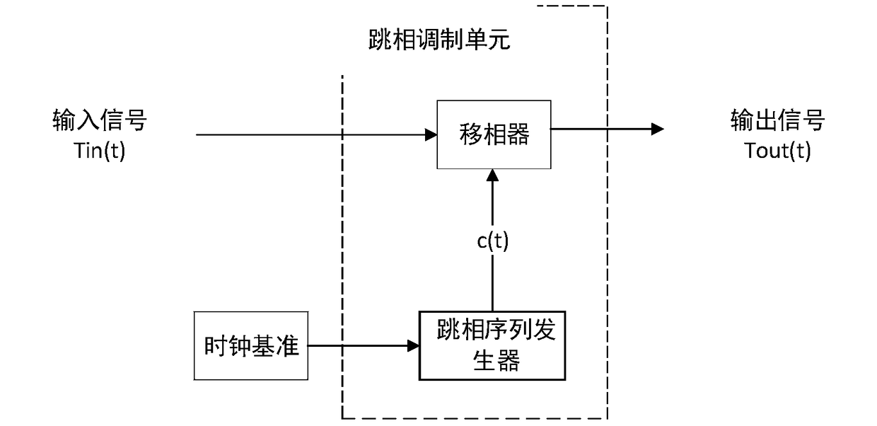
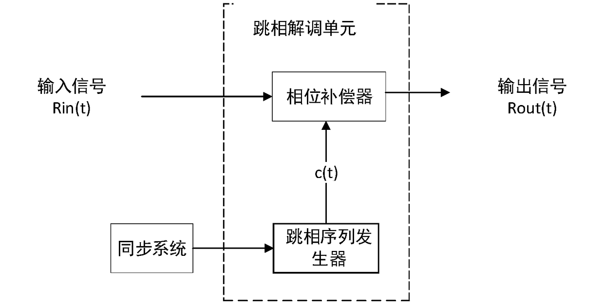
[0034] The invention discloses a signal modulation technology: modulation technology of carrier phase jump. The modulation can be directed to various signals, such as baseband signals, radio frequency signals, and carrier waves, all of which can be used as input signals of the modulation unit or the demodulation unit. This modulation ...


PUM


Abstract

The invention discloses signal modulation and demodulation methods and phase hopping modulation and demodulation units. The signal modulation method comprises the steps of 1, generating a phase hopping sequence via a phase hopping sequence generator under the control of a clock reference; and 2, performing corresponding phase shifting on the waveform of each chip in a signal to be modulated underthe control of the phase hopping sequence to acquire a modulated signal, wherein the phase hopping modulation unit comprises a phase shifter and a phase hopping sequence generator; the input end of the phase hopping sequence generator is used for being connected with the clock reference, and used for generating the phase hopping sequence under the control of the clock reference; the input end of the phase shifter is used for receiving the signal to be modulated; the control end of the phase shifter is connected with the output end of the phase hopping sequence generator; and after the phase shifter performs corresponding phase shifting on the waveform of each chip in the signal to be modulated under the control of the phase hopping sequence, the output end of the phase shifter outputs themodulated signal. According to the modulation method provided by the invention, the signal is equivalently subjected to twice PSK modulations, so that the modulated signal is close to noise characteristics, and the anti-detection performance of the signal can be improved.

Description

technical field [0001] The invention belongs to the technical field of signal modulation, and more specifically relates to a signal modulation and demodulation method and a phase-hopping modulation and demodulation unit. Background technique [0002] The confidentiality, reliability and anti-theft of key data such as aerospace telemetry, measurement and control, external measurement, and range experiments, as well as satellite navigation military signals, are crucial to national security. Enemy information detection will seriously threaten the launch and flight safety of various spacecraft. Therefore, the reliability requirements of wireless communication signals in special tasks and the importance of communication security make new wireless communication systems have to have good confidentiality capabilities. Modern wireless communication systems usually use frequency hopping and spread spectrum methods to resist interception and interference. With the improvement of inter...

Claims


Application Information

Patent Timeline
IPC IPC(8): H04B1/707H04B1/7075H04B1/7136H04B1/715H04L27/00
CPCH04B1/707H04B1/7075H04B1/7136H04B1/715H04B2001/7152H04L27/001
Inventor 唐祖平魏蛟龙杨明叶斌夏景圆刘昊李瑞博
Owner HUAZHONG UNIV OF SCI & TECH
Learn More