Clamping device and head mounted equipment

A technology of clamping device and clamping plate, which is applied to the structure of telephones, etc., can solve the problems of small application range and inability to put in headsets, etc., and achieve the effects of convenient operation, improved user experience, and simple and fast clamping process

Pending Publication Date: 2019-03-01
GEER TECH CO LTD
View PDF0 Cites 2 Cited by
  • Summary
  • Abstract
  • Description
  • Claims
  • Application Information

AI Technical Summary

Problems solved by technology

[0003] However, the existing mobile phone boxes are usually limited by the size of the box, and are only suitable for a small number of fixed models of mobile phones, and the scope of application is small
If the mobile phone is not the specified model, it cannot be put into the mobile phone box, so it cannot be put into the headset for use

Method used


Image

  • Clamping device and head mounted equipment
  • Clamping device and head mounted equipment
  • Clamping device and head mounted equipment

Examples


Embodiment 1

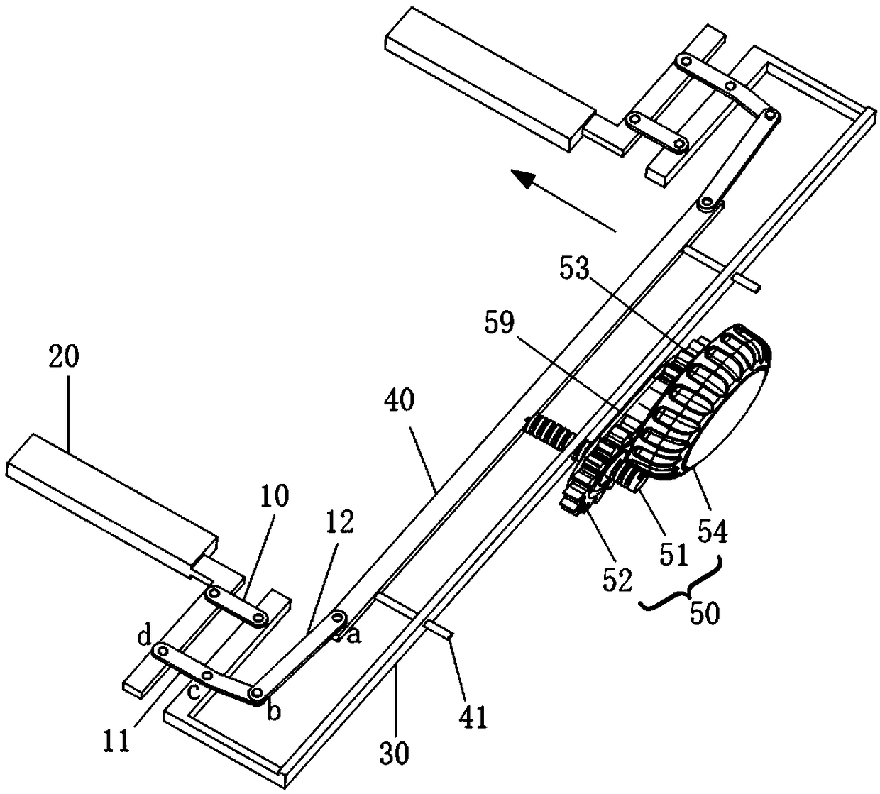
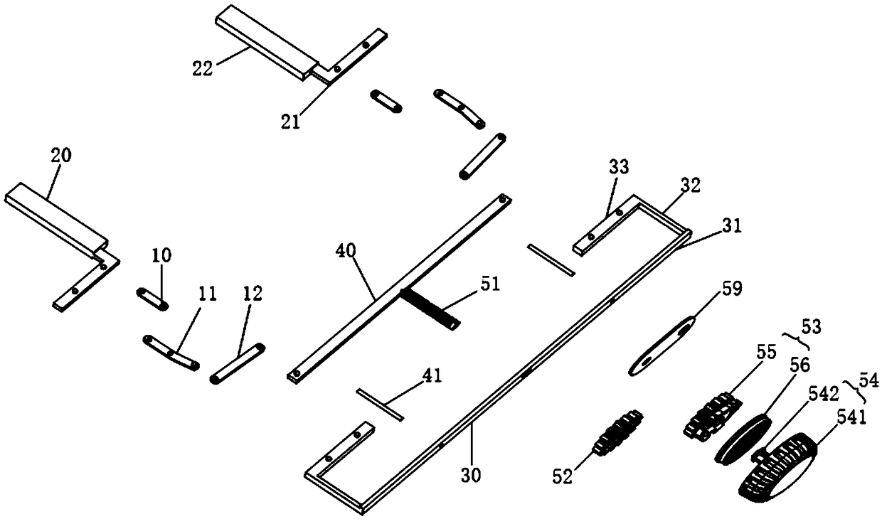
[0062] figure 1 It is a schematic plan view of the clamping device of the embodiment of the present invention, figure 2 It is a schematic diagram of an exploded structure of a clamping device according to an embodiment of the present invention, such as figure 1 and figure 2 shown.

[0063] The embodiment of the present invention provides a clamping device, comprising: at least one pair of clamping plates 20 with transmission components, a fixing bracket 30 , a driving rod 40 and an adjusting mechanism 50 .

[0064] Wherein, the pair of clamping plates 20 are arranged oppositely and form a clamping space.

[0065] The transmission assembly includes an orientation rod 10 , a first transmission rod 11 and a second transmission rod 12 . One end of the orientation rod 10 is rotatably connected to the clamping plate 20 , and the other end is rotatably connected to the fixing bracket 30 . The first transmission rod 11 is rotatably connected to the fixed bracket 30 , one end of...

Embodiment 2

[0096] Correspondingly, an embodiment of the present invention also provides a head-mounted device, including: the clamping device as in Embodiment 1.

[0097] In Embodiment 2 of the present invention, the clamping device can be used as a separate structure, for example, after the mobile phone is inserted into the clamping space, the clamping device is installed into the head-mounted device. The clamping device can also be set in the head-mounted device. One possible way is to refer to Figure 9 and Figure 10 , the head-mounted device includes a shell 60 , the clamping device is arranged in the shell 60 , and the fixed gear 56 and the fixed bracket 30 are fixedly connected with the shell 60 . The housing 60 has an adjustment hole, and the adjustment wheel 54 of the adjustment mechanism 50 protrudes from the adjustment hole. The housing 60 is provided with an opening 61 for the clamped part to enter and exit. After the clamped part enters the clamping space from the opening ...


PUM


Abstract

The embodiment of the invention discloses a clamping device and head mounted equipment. The clamping device comprises at least one pair of clamping plates respectively provided with a transmission component as well as a fixed support, a drive rod and a regulating mechanism, wherein the paired clamping plates are oppositely arranged and form a clamping space; each transmission component comprises an oriented rod, a first transmission rod and a second transmission rod; one end of each oriented rod is rotatably connected with the corresponding clamping plate, and the other end of each oriented rod is rotatably connected with the fixed support; each first transmission rod is rotatably connected on the fixed support, one end of each first transmission rod is rotatably connected with the corresponding clamping plate, and the other end of each first transmission rod is rotatably connected with one end of a corresponding second transmission rod; the other end of each second transmission gear is rotatably connected with the drive rod; the drive rod is connected with the regulating mechanism; and the regulating mechanism can drive the drive rod to do a straight reciprocating motion, and thedrive rod drives the paired clamping plates to be close to each other or far away from each other by virtue of the transmission components, so that the paired clamping plates clamp or release a clamped element contained in the clamping space.

Description

technical field [0001] Embodiments of the present invention belong to the technical field of wearable devices, and in particular, relate to a clamping device and a head-mounted device. Background technique [0002] With the popularity of VR (virtual reality, virtual reality) products, many VR headsets appear on the market. One of the head-mounted devices can insert a mobile phone into the device, and use the mobile phone as the main player for users to watch. In the existing equipment, the mobile phone is usually pre-fixed through the mobile phone box, and then the mobile phone box is loaded into the head-mounted device. [0003] However, existing mobile phone cases are usually limited by the size of the case, and are only suitable for a small number of fixed models of mobile phones, and the scope of application is relatively small. If the mobile phone is not of the specified model, it cannot be put into the mobile phone box, so that it cannot be put into the headset for u...

Claims


Application Information

Patent Timeline
Patent Type & Authority Applications(China)
IPC IPC(8): H04M1/04H04M1/05
CPCH04M1/04H04M1/05
Inventor 迟小程马青玉刘勃
Owner GEER TECH CO LTD
Why Eureka
Try Eureka