Video display device, television receiver and storage medium
A video display and video technology, which is applied in the direction of TV, color TV, color TV parts, etc., can solve the problem of multiplication and reduce the psychological burden
- Summary
- Abstract
- Description
- Claims
- Application Information
AI Technical Summary
Problems solved by technology
Method used
Image

Examples
Embodiment approach 1
[0037] (display device)
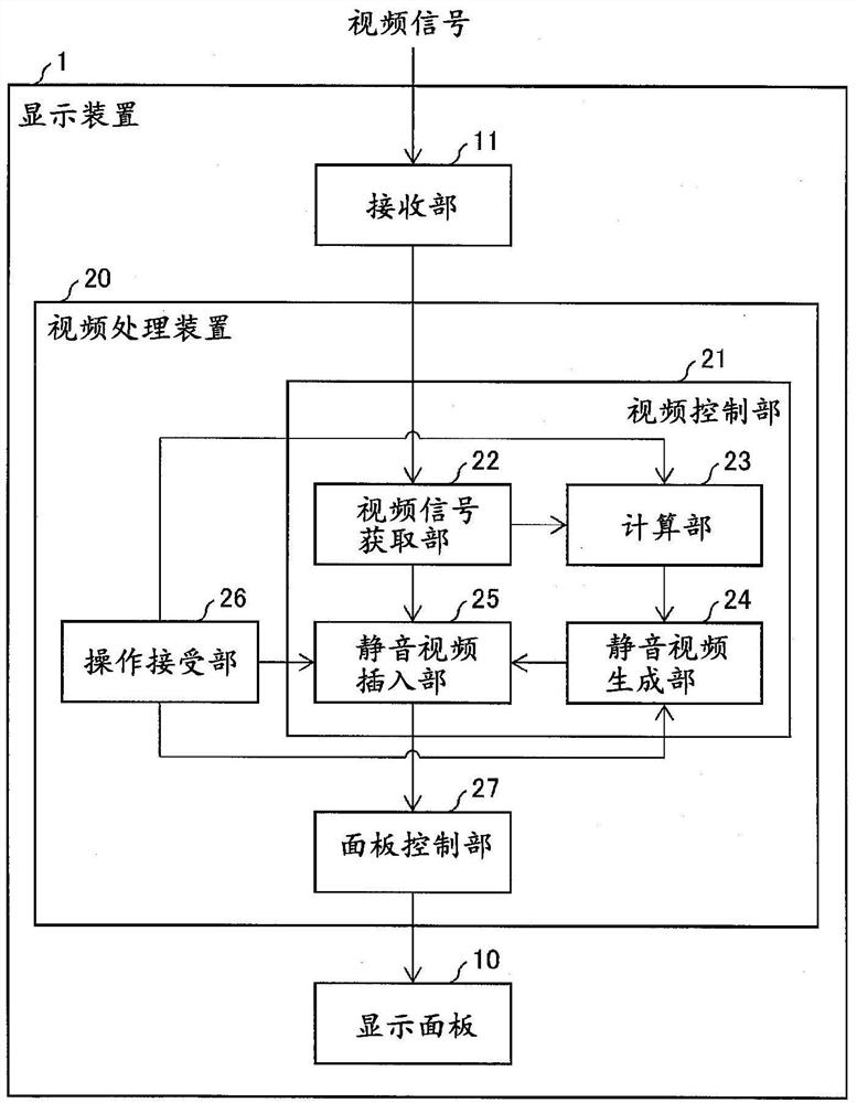
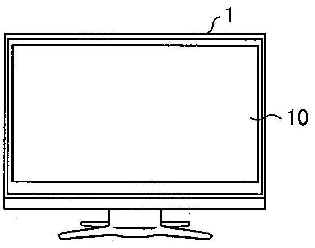
[0038] refer to figure 1 as well as figure 2 The display device 1 including the video processing device 20 according to the first embodiment will be described. figure 1 It is a block diagram showing the configuration of the display device 1 including the video processing device 20 according to the present embodiment. In addition, FIG. 2 is a front view showing the appearance of the display device 1. As shown in FIG. Such as figure 1 As shown, the display device 1 includes: a display panel 10 , a receiving unit 11 and a video processing device 20 . In addition, the display device 1 may be configured to include a tuner, and may be implemented as a television receiver. In addition, the display device may also be called a video display device.
[0039] (Video processing device)
[0040] The video processing device 20 is a device that sequentially outputs a plurality of frames constituting a video by decoding the video signal received by the receiv...
example 1
[0080] (Example 1: Calculation method using MaxFALL)
[0081] In this example, the calculation unit 23 calculates the maximum frame average brightness MaxFALL (Maximum Frame Average Light Level) from the acquired video data, and sets the calculated MaxFALL as the perceived brightness value. Here, MaxFALL refers to the maximum value of the average luminance in all the frames constituting the video, and the algorithm is defined in accordance with CEA861.3. Figure 6 Pseudocode for calculating MaxFALL is shown.
[0082] Such as Figure 6As shown, the calculation unit 23 converts (R', G', B') which is a non-linear pixel value into cd / m 2 Linear brightness value (R, G, B) in units of (candela per square meter). And the maximum value among (R, G, B) is set as the maximum brightness value maxRGB of the pixel.
[0083] Also, the calculation unit 23 sets the average of the maximum luminance values maxRGB of all pixels included in the effective image area as the average luminanc...
example 2
[0086] (Example 2: How to exclude black screens and white screens)
[0087] When all frames included in the video sequence include a frame having a white screen (a screen whose average luminance is equal to or greater than the threshold value Wt (Bk<Wt)), the value of MaxFALL becomes a very large value. The calculated video feature quantity is not suitable as a feature of the video sequence as a whole.
[0088] In this example, the calculation unit 23 calculates Perceived brightness value. By using this example for the calculation of the perceived brightness value, it is possible to calculate a more appropriate perceived brightness value.
[0089] FIG. 7 shows a pseudo code for the calculation unit 23 to calculate the perceptual luminance value according to this example. As shown in FIG. 7 , the calculation unit 23 calculates the linear luminance value Y (linear luminance value) of the pixel according to a pixel included in the active image area (active image area) of a cer...
PUM
 Abstract
Description
Claims
Application Information
 - R&D
- Intellectual Property
- Life Sciences
- Materials
- Tech Scout
- Unparalleled Data Quality
- Higher Quality Content
- 60% Fewer Hallucinations
Browse by: Latest US Patents, China's latest patents, Technical Efficacy Thesaurus, Application Domain, Technology Topic, Popular Technical Reports.
© 2025 PatSnap. All rights reserved.Legal|Privacy policy|Modern Slavery Act Transparency Statement|Sitemap|About US| Contact US: help@patsnap.com