
Method of making a throttle body

A throttle body and throttle valve technology, applied in the directions of additive manufacturing, engine control, process efficiency improvement, etc., can solve the problems of long lead time and high cost, and achieve the effect of low cost

Inactive Publication Date: 2019-03-05
GM GLOBAL TECH OPERATIONS LLC
View PDF4 Cites 0 Cited by
  • Summary
  • Abstract
  • Description
  • Claims
  • Application Information

AI Technical Summary

Problems solved by technology

As a result, each design variant has a higher cost and a longer lead time for casting preparation for each

Method used


Image

  • Method of making a throttle body
  • Method of making a throttle body
  • Method of making a throttle body

Examples


Embodiment Construction

[0014] Exemplary embodiments will now be described more fully with reference to the accompanying drawings.

[0015] Example embodiments are provided so that this disclosure will be thorough, and will fully convey the scope to those who are skilled in the art. Numerous specific details are set forth, such as examples of specific components, devices and methods, in order to provide a thorough understanding of embodiments of the invention. It will be apparent to those skilled in the art that specific details need not be employed, that example embodiments may be embodied in many different forms and that these specific details should not be construed to limit the scope of the invention. In some example embodiments, well-known methods, well-known device structures, and well-known technologies are not described in detail.

[0016] The terminology used herein is for the purpose of describing particular exemplary embodiments only and is not meant to be limiting. As used herein, the s...


PUM


Abstract

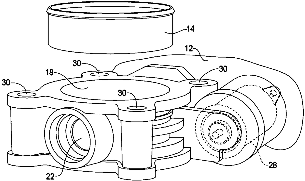
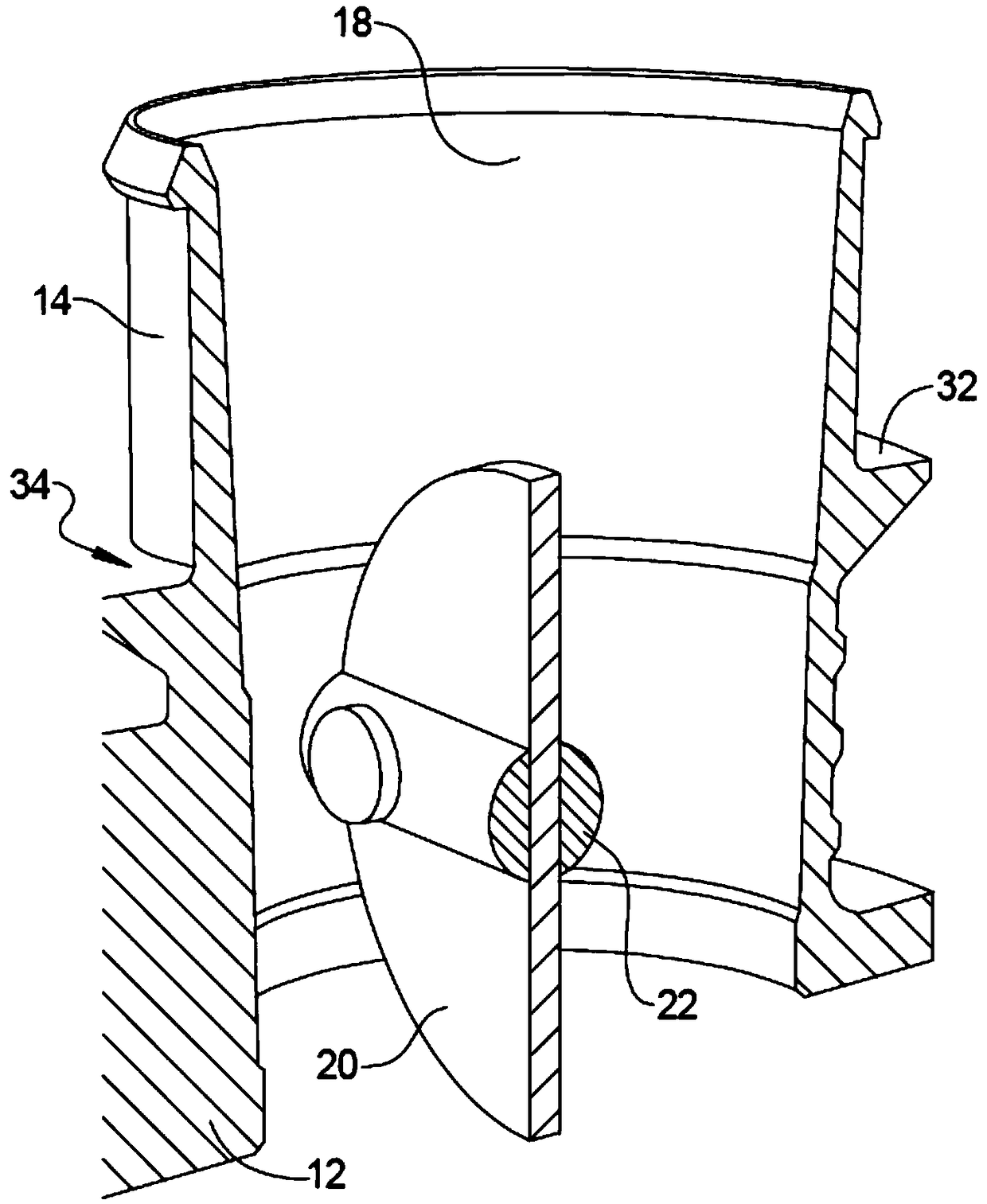
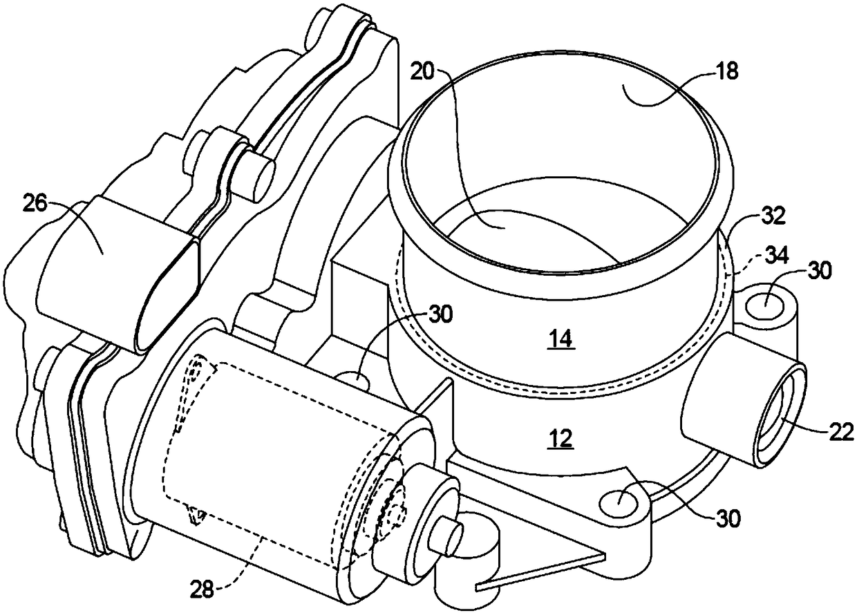
A method of making a throttle body assembly, includes casting a main body portion having a passage there through and mounting features for pivotally mounting a throttle valve within the passage. An annular spigot is formed by 3-dimensional printing and is welded to the main body portion in order to provide a quicker less expensive method of prototyping.

Description

technical field [0001] The present invention relates to a method of manufacturing a throttle body, and more particularly, to a method of manufacturing a throttle body for rapid prototyping. Background technique [0002] This section provides background information related to the present disclosure which is not necessarily prior art. [0003] Throttle bodies are commonly used in the intake system of internal combustion engines to control the flow of air to the engine in response to driver activation of the accelerator pedal. The throttle blade is mounted in the throttle body which regulates airflow. Movement of the accelerator pedal may be transmitted via a cable to a linkage that moves the throttle blade. In an electronic throttle control system, an electric motor may be used to control the throttle linkage, which responds to a throttle pedal position sensor. The engine control unit determines the throttle opening based on accelerator pedal position and input from other e...

Claims


Application Information

Patent Timeline
Patent Type & Authority Applications(China)
IPC IPC(8): F02D9/10B22F3/105B33Y80/00
CPCB33Y80/00F02D9/107F02D9/1085B22F10/00B22F10/20F02D2200/602F02D11/106F02D9/1065F02D2009/0267F02D2009/0279F02D2009/0255Y02P10/25F02D2011/102
Inventor L·巴特福奥克
Owner GM GLOBAL TECH OPERATIONS LLC
Learn More