Crucible for the crystallization of silicon and process for making the same

a technology of crystallization and crucibles, which is applied in the direction of separation processes, lighting and heating apparatus, furnaces, etc., can solve the problems of contaminating silicon with oxygen, cracking on cooling, and contaminating silicon with carbon, so as to improve the stability of suspension, improve one or more characteristics, and high reactivity of binder

Inactive Publication Date: 2012-10-30
VESUVIUS USA CORP
View PDF10 Cites 4 Cited by
  • Summary
  • Abstract
  • Description
  • Claims
  • Application Information

AI Technical Summary

Benefits of technology

[0012]It is therefore desirable to provide a crucible which does not present the above problems comprising a coating which is stronger (avoid peeling and flake off), with improved mechanical wear resistance, fast and cheap to produce while preventing chemical reaction between molten silicon and the crucible and maintaining the additional requirements in terms of oxygen content. It has now been found that these problems can be solved with a crucible for the crystallization of silicon comprising a) a base body comprising a bottom surface and side walls defining an inner volume; b) a silicon nitride based protective coating at the surface of the side walls facing the inner volume, said coating comprising 80 to 95 wt. % of silicon nitride and 5 to 20 wt. % of a low temperature mineral binder, the total oxygen content ranging from 5 to 15% by weight. Preferably, the low temperature binder is a silica based binder. Silicon oxinitride powder and preferably a combination of silicon nitride and silicon oxinitride powders can also be used. The silicon oxinitride powder is generally comprised between 5 and 20 wt. %. The silicon oxinitride powder may be a recycled oxinitride or a water activated oxinitride. One considerable advantage of the present invention is that the amount content of oxygen in the silicon nitride powder is not critical anymore and the use of a powder comprising a certain amount of oxygen as for instance a recycled powder can be considered. The crystallographic phase of the silicon nitride powder can be α or β.
[0013]The expression “low temperature binder” is used herein to refer to a binder that creates a bond at a temperature lower than the temperature required to oxidise the silicon nitride. Preferably the bond is created at a temperature lower than 800° C. and more preferably lower than 500° C.
[0014]By mineral binder, it is intended to refer to a binder comprising a mineral base having residues that always give a mineral form plus carbon or not. This is in contrast to organic binders such as CMC (carboxymethylcellulose), glue, and surfactants that give residues which are only carbon. The high reactivity of the binder is partly given by the mineral base.
[0015]The granulometry of the silicon nitride or silicon oxinitride powder is generally submicronic, particle size ≦1 μm. However, a blend of nitride powders comprising different particle sizes and notably comprising coarser particles or grains comprised between 2 and 50 μm, preferably between 2 and 5 μm can also be used. The blend is chosen so as to improve one or more characteristics. The blend can improve the stability of the suspension and / or further increase the adhesion of the coating onto the crucible. In case another coating is present under and / or on the top of the nitride coating according to the present invention, a blend can also facilitate the adhesion between the different coatings. The other coating can be for instance a silica based coating as described in patent application WO2005 / 106084 and co-pending application PCT / EP2006 / 006347. The quantity of coarser particles is generally comprised between 20 and 50% by weight with respect to the submicronic particles. Coarser silicon nitride powder is less expensive, the introduction of such powder also reduces the cost of the coating.
[0016]Depending upon the application, the protective coating will have a thickness of 50 μm to 500 μm, preferably of 200 to 500 μm. To avoid any contamination, it is essential that the protective coating be of very high purity with an ultra-low carbon content.
[0017]This new technology is based on the use of limited and controlled amounts of oxygen in the coating. The oxygen is introduced with a low temperature mineral binder (sol gel, organo-metallic, nano-particles, micro-flocculent, non miscible solutions, micro-emulsions, oxides). A very low temperature bonding phase is created throughout the coating increasing the mechanical wear resistance of the protective coating while keeping the desired properties of the silicon nitride. Risk of peeling and flaking off of the coating is much reduced.

Problems solved by technology

There are problems in using silica, however, as a crucible for the production of silicon by this method.
Oxygen will contaminate the silicon.
Carbon will contaminate the silicon.
This adhesion, combined with a difference in coefficients of thermal expansion between the two materials, creates stress in the silicon ingot, causing it to crack on cooling.
In addition, the use of chemical vapor deposition, solvent evaporation, high-temperature flame treatment, and other expensive and complex means are mentioned for application of crucible coatings.
However, the silicon nitride coating itself can lead to problems.
The thickness of the silicon nitride coating necessary to prevent the silicon from reacting with the silica crucible is quite important (about 300 μm) making thereby the coating operation expensive and time consuming.
Further, this silicon nitride coating is mechanically weak and can peel or flake off during or even before use.
The oxidation of the silicon nitride into silicon oxide increases the quantity of oxygen in the coating and leads to the problem mentioned above.
In addition the level of oxidation and resulting amount of oxygen is not easy to control.
However, some problems remain.
As there is no oxidation of the coating, the coating remains pulverulent and is easily damaged when liquid silicon is charged into the crucible.

Method used


Image

  • Crucible for the crystallization of silicon and process for making the same
  • Crucible for the crystallization of silicon and process for making the same

Examples


Embodiment Construction

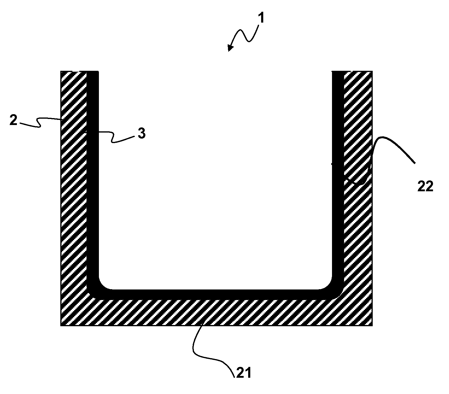
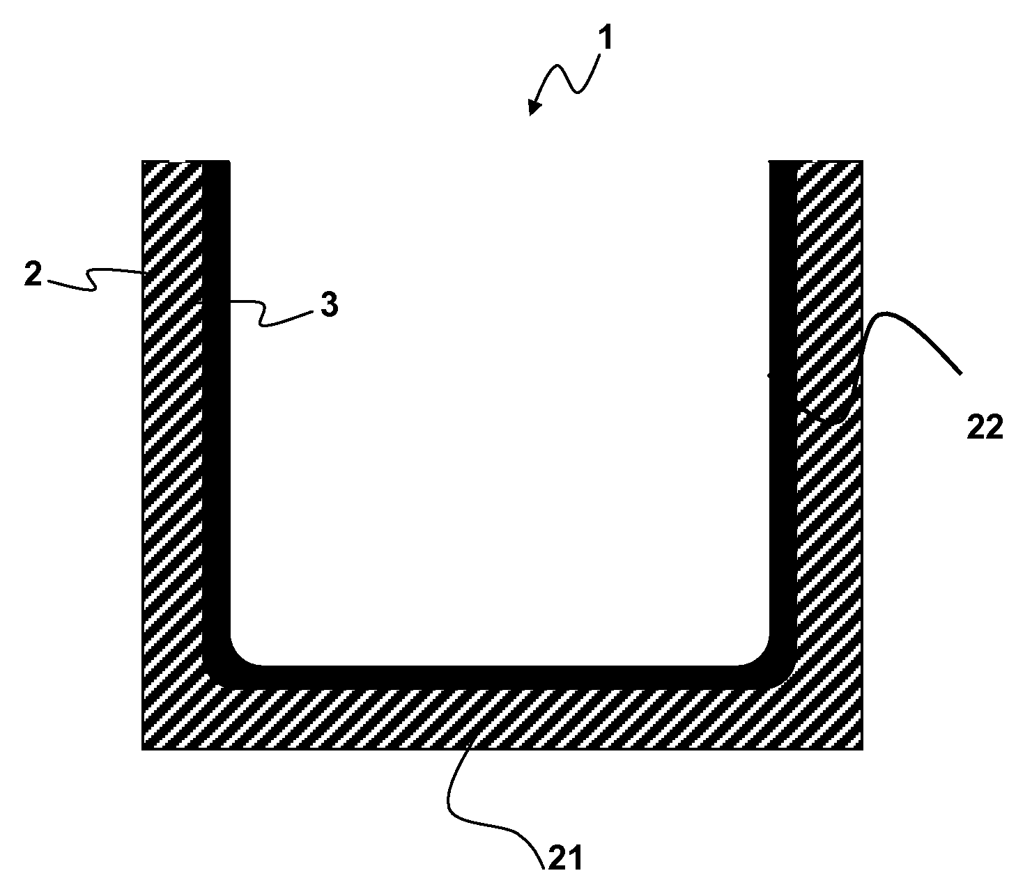
[0029]The invention will now be described with reference to the enclosed figure which only serves to illustrate the invention and is not intended to limit its scope. On the figure, the crucible is designated with reference number 1. It comprises a base body 2 comprising a bottom surface 21 and side walls 22 which define an inner volume for the crystallization of silicon. The crucible comprises a protective layer 3 which is comprised of 80 to 95 wt. % of silicon nitride, 5 to 20 wt % of a low temperature mineral binder, the total oxygen content being higher than 5% by weight at the surface of the side walls 22 facing the inner volume.

[0030]The invention will now be illustrated by way of examples according to the invention and comparative examples. The process to apply the coating on the base body can be achieved in different ways. The composition depends on the method chosen.

[0031]The first preferred method (reactive layer) comprises the step of[0032]mixing silicon nitride powders an...


PUM

PropertyMeasurementUnit
thicknessaaaaaaaaaa
thicknessaaaaaaaaaa
diameteraaaaaaaaaa

Abstract

A protective coating is prepared for, and applied to, crucibles used in the handling of molten materials that are solidified in the crucible and then removed as ingots. Crucibles containing this protective coating may be used for the solidification of silicon. The coating has a specified oxygen content and contains a mineral binder and silicon nitride or silicon oxynitride.

Description

FIELD OF THE INVENTION[0001]The invention relates to a crucible for the crystallization of silicon and to the preparation and application of a protective coating for crucibles used in the handling of molten materials that are solidified in the crucible and then removed as ingots, and more particularly to protective coating for crucibles used in the solidification of polycrystalline silicon.BACKGROUND OF THE INVENTION[0002]Crucibles (for instance made of fused silica, silicon carbide, quartz, silicon nitride, reaction bonded silicon nitride, or graphite) are typically used in solidification of polycrystalline silicon. Silica is chosen primarily for high purity and availability. There are problems in using silica, however, as a crucible for the production of silicon by this method.[0003]Silicon in its molten state will react with the silica crucible that is in contact with it. Molten silicon reacts with silica to form silicon monoxide and oxygen. Oxygen will contaminate the silicon. S...

Claims


Application Information

Patent Timeline
Patent Type & Authority Patents(United States)
IPC IPC(8): C30B15/10
CPCC04B35/584C04B35/6264F27B14/10C30B15/10C30B11/002C04B35/6316C04B41/009C04B41/5066C04B41/87C04B41/5089C04B41/4539C04B41/4554C04B41/5035C04B35/14C04B2235/80C04B2235/5445C04B2235/5436C04B2235/483C04B2235/3873C04B2235/3427C04B2235/3418C30B11/00
Inventor RANCOULE, GILBERT
Owner VESUVIUS USA CORP
Why Eureka
Try Eureka