
Damping mechanism for shift selector assembly and shift selector assembly comprising said damping mechanism

A gear selector and damping mechanism technology, which is applied in the field of damping mechanisms, can solve problems such as excessive friction, and achieve the effects of prolonging the usable life and reducing costs

Active Publication Date: 2019-03-05
FICO TRIAD
View PDF9 Cites 2 Cited by
  • Summary
  • Abstract
  • Description
  • Claims
  • Application Information

AI Technical Summary

Problems solved by technology

[0005] The main disadvantage of prior art solutions is that the gear lever has to overcome excessive friction with the sound-deadening elements in the contoured surface

Method used


Image

  • Damping mechanism for shift selector assembly and shift selector assembly comprising said damping mechanism
  • Damping mechanism for shift selector assembly and shift selector assembly comprising said damping mechanism
  • Damping mechanism for shift selector assembly and shift selector assembly comprising said damping mechanism

Examples


Embodiment Construction

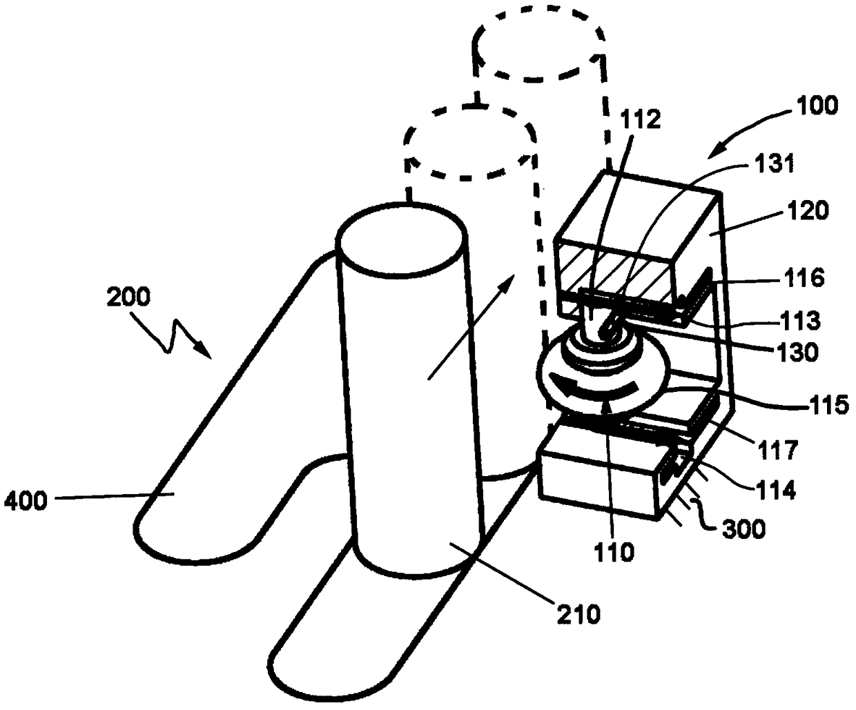
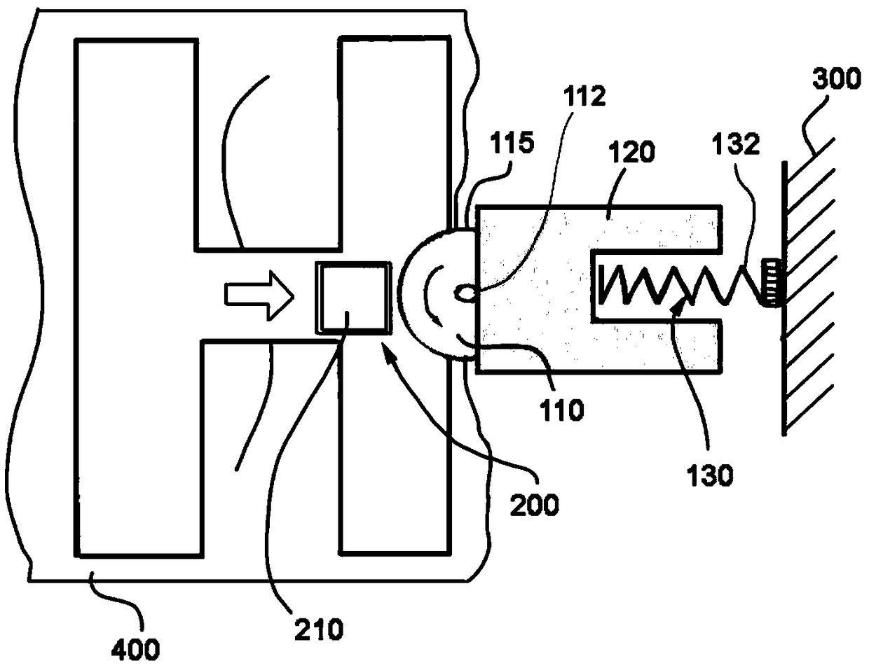
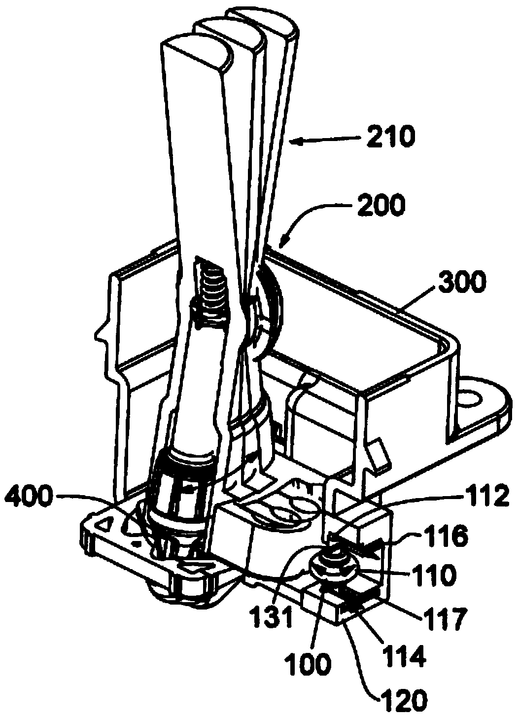
[0028] Hereinafter, non-limiting examples of the present damping mechanism are described with reference to the accompanying drawings. In the examples described, like reference numerals refer to like parts throughout the several views of the drawings.

[0029] The damping mechanism 100 is shown incorporated in a gear selector assembly 200 of a motor vehicle transmission. The gear selector assembly 200 includes a fixed part 300 and a movable part, which corresponds to the shift lever 210 in this example. The shift lever 210 is movable relative to the fixed part 300 . In this example, the stationary component 300 is part of the shifter cover of the gear selector assembly 200 , although the stationary component 300 could be a component attached to the shifter cover.

[0030] Such as image 3 and Figure 4 As shown, the shift lever 210 is movable relative to the stationary member 300 in different directions that are biased onto the contoured surface 400 . Contoured surface 400...


PUM


Abstract

The invention relates to a damping mechanism for shift selector assembly and the shift selector assembly. The damping mechanism (100) comprises a damping element (110) suitable for absorbing impacts from a movable part (210) of the shift selector assembly (200), and a support member (120) to which the damping element (110) is rotatably mounted.

Description

technical field [0001] The present disclosure relates to a shift-by-wire device for controlling a motor vehicle transmission, and more particularly, to a damping mechanism for absorbing shock from a gear lever during use. Background technique [0002] A motor vehicle transmission, in particular a motor vehicle automatic transmission, includes a shift-by-wire device (also known, for example, as an ATX SbW shifter) comprising gears operable to select gears corresponding to different transmission gears. shift lever in gear position. A moveable spring-biased plunger is housed in the shift lever to slide on contoured surfaces when the shift lever is moved to select a shift position to provide a user with a shift feel. [0003] In use, the shift lever is moved onto said contoured surface and the spring plunger is pressed into the different shift positions defined in this contoured surface against the force generated by the spring element. During actuation of the gear lever, for ...

Claims


Application Information

Patent Timeline
Patent Type & Authority Applications(China)
IPC IPC(8): F16H59/02
CPCF16H59/0208F16H2061/241F16H59/0278F16H59/10F16H61/24
Inventor J·M·科洛姆
Owner FICO TRIAD
Learn More