

Unlocking method, device and system
A technology for unlocking and receiving devices, which is applied in the fields of unlocking methods, devices and systems, and can solve problems such as high costs and achieve the effect of solving high costs and reducing costs
- Summary
- Abstract
- Description
- Claims
- Application Information
AI Technical Summary
Problems solved by technology
Method used
Image

Examples
Embodiment 1
[0036] According to the embodiment of the present application, a method embodiment of an unlocking method is also provided. It should be noted that the steps shown in the flow chart of the accompanying drawings can be executed in a computer system such as a set of computer-executable instructions, and, Although a logical order is shown in the flowcharts, in some cases the steps shown or described may be performed in an order different from that shown or described herein.
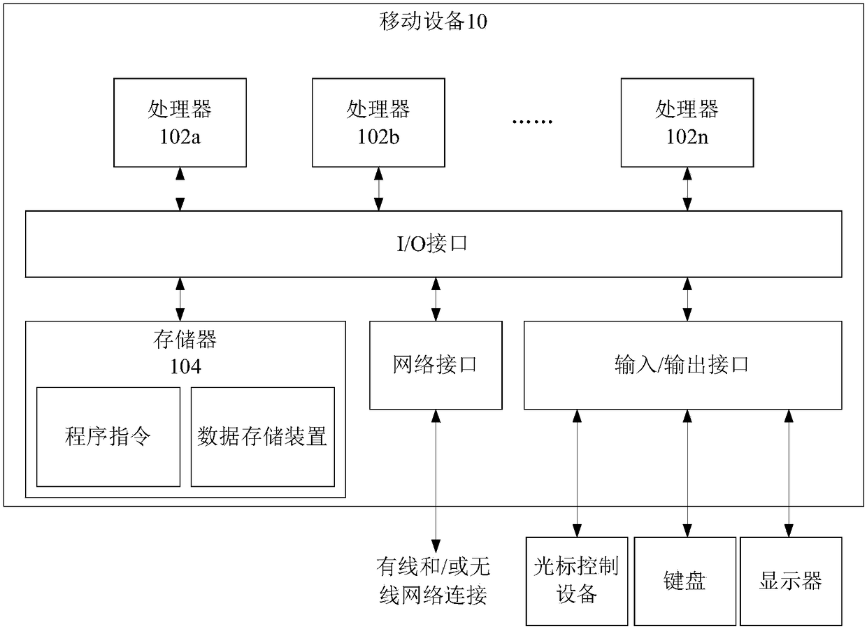
[0037] The method embodiment provided in Embodiment 1 of the present application may be executed in a mobile terminal, a computer terminal, or a similar computing device. figure 1 It shows a hardware structure block diagram of a mobile device (or computer terminal) for realizing the unlocking method. like figure 1 As shown, the mobile device 10 (or computer terminal) may include one or more (shown by 102a, 102b, ..., 102n in the figure) processor 102 (the processor 102 may include but not limited to a micro...
Embodiment 2
[0133] Under the above operating environment, this application provides such Figure 5 The unlocking method shown. Figure 5 It is a flowchart of an unlocking method according to Embodiment 2 of the present application. The method comprises the steps of:
[0134] Step S302, acquiring status change data of the flash receiving device.
[0135] In the above step S302 of this embodiment, the state change data is generated by the flash receiving device after receiving the flash signal from the light-emitting component. The flash receiving device in this embodiment may include at least one of the following: a solar cell, a photodiode, and a camera. The light emitting component may refer to a flashlight of the mobile phone.
[0136] As an optional implementation manner, in the case that the flash receiving device includes a solar cell, the state change data includes a voltage change value output by the solar cell.
[0137] As shown in 4(d), under the action of the light-emitting...
Embodiment 3
[0152] According to an embodiment of the present application, an unlocking device for implementing the above unlocking method is also provided, such as Image 6 As shown, the device includes: a first acquisition unit 602 , a conversion unit 604 and a control unit 606 .
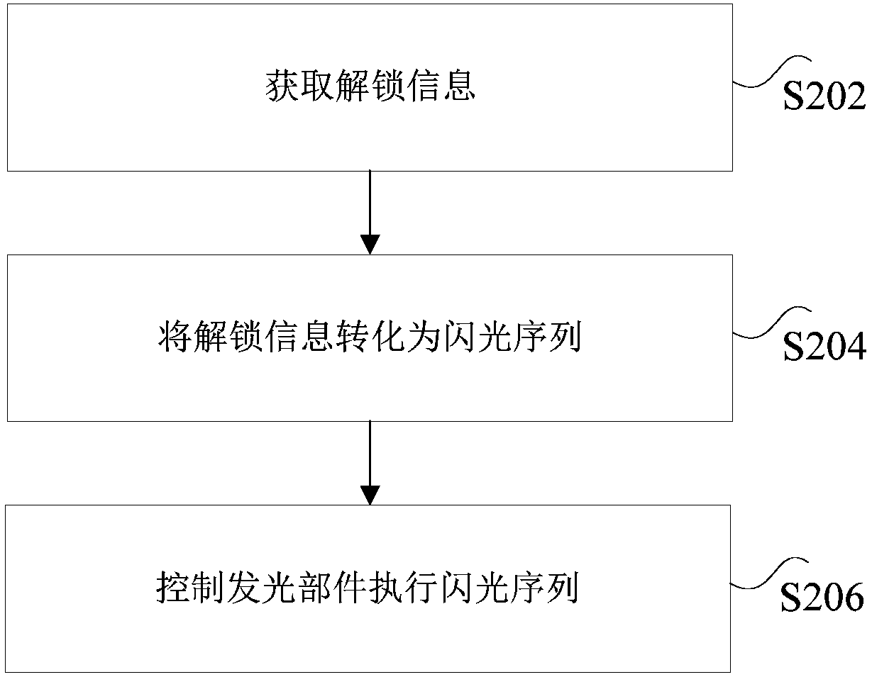
[0153] Wherein, the first obtaining unit 602 is used to obtain unlocking information; the conversion unit 604 is used to convert the unlocking information into a flashing sequence; the control unit 606 is used to control the light-emitting component to execute the flashing sequence.
[0154] It should be noted here that the above-mentioned first acquisition unit 602, conversion unit 604 and control unit 606 correspond to Step S202 to Step S206 in Embodiment 1, and the examples and application scenarios realized by the three modules are the same as the corresponding steps, But it is not limited to the content disclosed in the first embodiment above. It should be noted that, as a part of the device, the above m...
PUM
 Abstract
Description
Claims
Application Information