SMD component flipping device and method

A technology of chip components and components, which is applied in the direction of assembling printed circuits, electrical components, electrical components, etc., can solve the problems of time-consuming and energy-consuming, small size of chip components, and influence on efficiency, and achieve improvement Production efficiency, increased automation, and reduced human involvement

Active Publication Date: 2021-07-16
CHANGCHUN INST OF OPTICS FINE MECHANICS & PHYSICS CHINESE ACAD OF SCI
View PDF3 Cites 0 Cited by
  • Summary
  • Abstract
  • Description
  • Claims
  • Application Information

AI Technical Summary

Problems solved by technology

[0004] In the process of manually placing components, the SMD components are extremely small, especially some SMD resistors that need to be placed upwards. Once the components are not facing up, the production personnel can only use tweezers to repeatedly pick the components. Turning it over is very time-consuming and energy-intensive, which greatly affects efficiency

Method used


Image

  • SMD component flipping device and method
  • SMD component flipping device and method

Examples


Embodiment Construction

[0018] In order to make the object, technical solution and advantages of the present invention clearer, the present invention will be further described in detail below in conjunction with the accompanying drawings and specific embodiments. It should be understood that the specific embodiments described here are only used to explain the present invention, but not to limit the present invention.

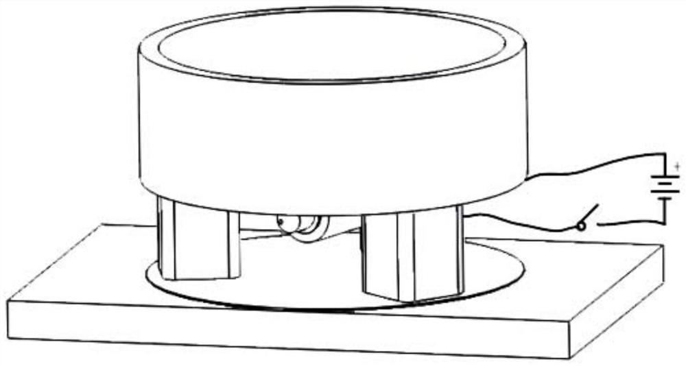
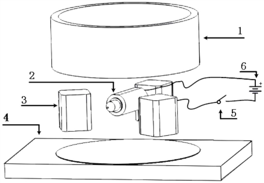
[0019] Please refer to figure 1 and figure 2 , the patch component flipping device provided by the embodiment of the present invention includes: a component tray 1, a base 4, a support sponge 3, a vibration motor 2, a click switch 5 and a dry battery pack 6, the component tray 1 is used to place components to be used for patching, the vibration motor 2 is installed at the center of the lower part of the component tray 1, and the component tray 1 is installed on the base 4 through the support sponge 3 On the seat, the vibration motor 2, the click switch 5, and the dry battery pack 6 ...


PUM


Abstract

The invention discloses a surface-mounting device for patch components, comprising: a component tray, a base, a support sponge, a vibrating motor, a click switch and a dry battery pack, and the component tray is used for placing the components to be used for patching components, the vibration motor is installed in the central position of the lower part of the component tray, and the component tray is installed on the base through the support sponge, the vibration motor, click switch, dry battery The groups are connected in series, and the dry battery group provides electric energy for the vibration motor. The invention is used in the occasions where small batches of chips need to be placed manually on the SMT production line, and is a device capable of turning over the chip components.

Description

technical field [0001] The invention relates to the technical field of electronic assembly, and is used in an SMT production line where small batches of chips need to be placed manually, and is a device and method capable of turning over chip components. Background technique [0002] SMT technology, that is, surface mount technology, is currently the most popular technology and process in the electronics assembly industry. It is a circuit assembly technology that mounts non-lead or short-lead surface mount components on the surface of a printed circuit board or other substrates, and solders and assembles them by methods such as reflow soldering. The general SMT process can be concisely expressed as: solder paste printing, parts placement, reflow soldering, inspection and maintenance and other steps. [0003] However, the soldering of printed circuit boards in the field of scientific research and military industry has the characteristics of "multiple varieties and small batc...

Claims


Application Information

Patent Timeline
Patent Type & Authority Patents(China)
IPC IPC(8): H05K3/34H05K13/04
CPCH05K3/34H05K13/046
Inventor 付柯楠石宝松聂磊
Owner CHANGCHUN INST OF OPTICS FINE MECHANICS & PHYSICS CHINESE ACAD OF SCI
Why Eureka
Try Eureka