
A rotary drying device

A rotating and driving rod technology, which is applied in seed and rhizome treatment, agriculture, application, etc., can solve the problems of affecting yield, easily scalding seeds, reducing germination rate, etc., and achieves convenient installation, uniform seed drying, and high utilization efficiency Effect

Active Publication Date: 2021-06-11
李罡
View PDF4 Cites 0 Cited by
  • Summary
  • Abstract
  • Description
  • Claims
  • Application Information

AI Technical Summary

Problems solved by technology

[0004] However, the harvesting time of rice seeds is still in the high temperature period in autumn. Sometimes the weather temperature is above 35°C. In the afternoon, the temperature accumulated on the cement field or asphalt road will be very high, which is easy to burn the seeds and reduce the germination rate.
Therefore, it is very unfavorable to maintain the quality of the seeds to expose the rice seeds on the open-air cement field or asphalt road, especially in continuous high temperature weather; in addition, after the rice seeds are piled up to a certain height, the rice in the lower layer is often unable to be exposed to the sun. However, this will result in uneven drying of seeds and poor results, which will affect the yield in the later period.

Method used


Image

  • A rotary drying device
  • A rotary drying device
  • A rotary drying device

Examples


Embodiment 1

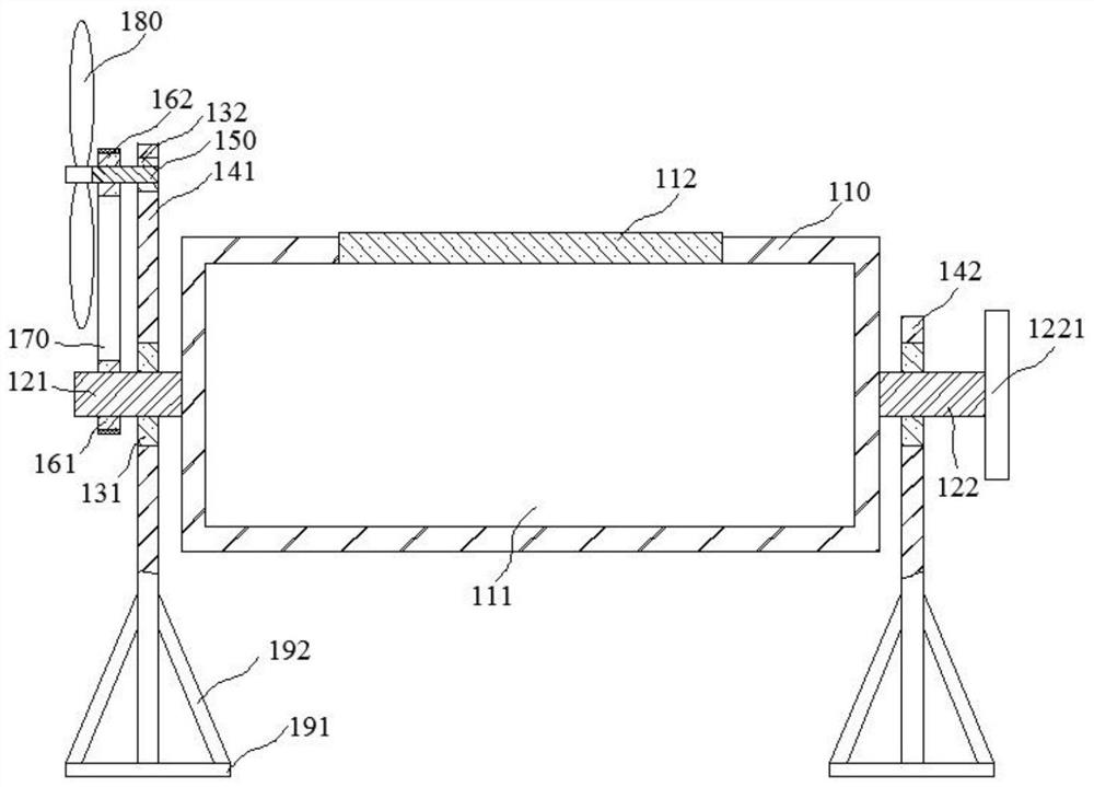
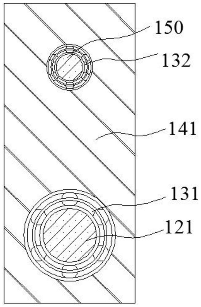
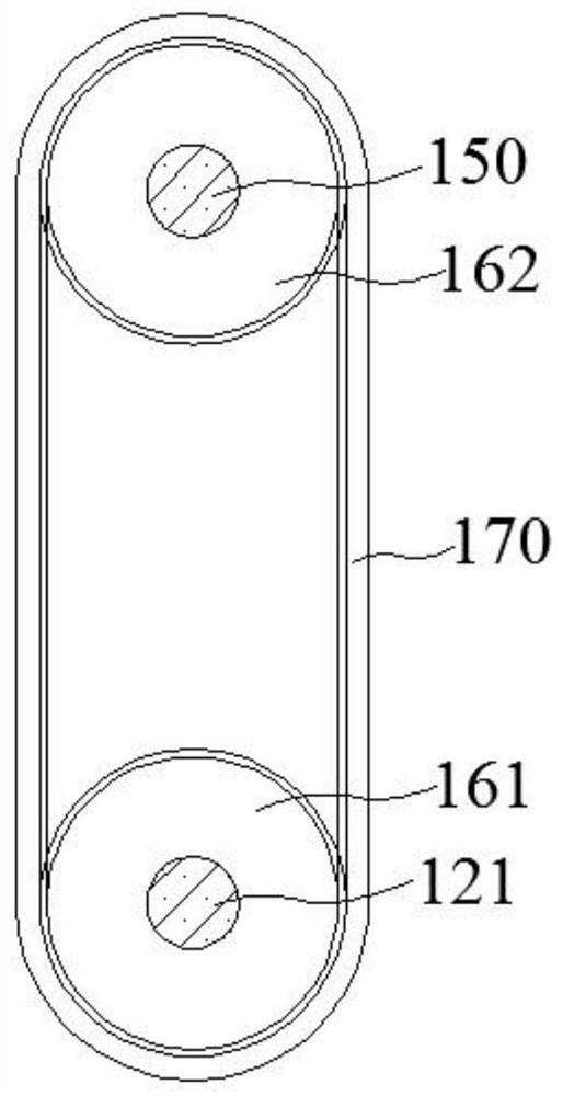
[0039] Such as figure 1 , figure 2 and image 3 As shown, the present embodiment provides a drying device that can simultaneously utilize solar energy and wind energy, which includes a horizontally arranged transparent cylinder 110, a cylinder cavity 111 is provided in the transparent cylinder 110, and a transparent cylinder 110 side wall is provided with The cylinder cover 112; the left and right ends of the transparent cylinder 110 are respectively axially provided with a first drive rod 121 and a second drive rod 122, and the first drive rod 121 and the second drive rod 122 are rotatably connected to the first vertical rod 141 and the second vertical rod 141 respectively. On the two vertical bars 142; the first vertical bar 141 is also rotatably connected with a cross bar 150, the cross bar 150 is located above the first drive bar 121 and higher than the transparent cylinder 110; the first drive bar 121 and the cross bar 150 pass through The toothed belt 170 drives, and ...

Embodiment 2

[0050] Such as Figure 4 , Figure 5 , Figure 6 and Figure 7 As shown, this embodiment provides a seed drying device for conveniently turning seeds, including a horizontally arranged transparent cylinder 110, a cylinder cavity 111 is provided inside the transparent cylinder 110, and one side of the cylinder cavity 111 is open and a cylinder cover 112 is provided. The transparent cylinder 110 is provided with more than two rings 210 in the circumferential direction, part of the rings 210 are located in a housing chamber 221, the housing chamber 221 is located in the support seat 220, and the support seat 220 is located below the transparent cylinder 110; the opening of the housing chamber 221 is upward Moreover, a plurality of balls 230 are provided on the bottom surface and the side wall, and the plurality of balls 230 are attached to the part of the ring 210 .

[0051] Through the cooperation of more than two rings 210 and the balls 230 in the corresponding housing chamb...

Embodiment 3

[0061] Such as Figure 8 , Figure 9 and Figure 10 As shown, the present embodiment provides a kind of drying device, including a horizontally arranged transparent cylinder 110, a cylinder cavity 111 is provided inside the transparent cylinder 110, one side of the cylinder cavity 111 is open and a cylinder cover 112 is provided; the transparent cylinder The right end of 110 is provided with a ring 210 in the circumferential direction, and part of the ring 210 is rotatably located in a housing chamber 221, the housing chamber 221 is located in the support seat 220, and the support seat 220 is located below the transparent cylinder 110; the left end of the transparent cylinder 110 is axially provided with The first driving rod 121, the first driving rod 121 is rotatably connected to the first vertical rod 141, the bottom end of the first vertical rod 141 is located in an installation cavity 311, and the installation cavity 311 is located in the support block 310; the installat...


PUM


Abstract

The invention relates to the technical field of drying devices, and relates to a rotary drying device. A cylinder chamber is provided in a transparent cylinder, and a cylinder cover is provided in the cylinder chamber; a ring is provided at the right end of the transparent cylinder, and part of the ring is rotatable. It is located in a receiving cavity, and the receiving cavity is located in the supporting seat; the left end of the transparent cylinder is provided with a first driving rod, which is rotatably connected to the first vertical rod; the first vertical rod is also rotatably connected to the horizontal rod, and the horizontal rod Located above the first drive rod and higher than the transparent cylinder; the first drive rod and the cross bar are driven by a toothed belt, and one end of the cross bar is detachably provided with a blade; the bottom end of the first vertical rod is provided with a block, and the block There is a card slot inside, the card head is located in the card slot, and an adjustment rod is provided under the card head. The bottom end of the adjustment rod is located in the installation cavity, and the installation cavity is located in the support block; there is a worm wheel in the installation cavity, and the worm wheel is threaded. At the bottom end of the adjusting rod, the worm wheel cooperates with the worm, and the worm rotatably passes through the support block and is connected with the running wheel. The invention can effectively dry seeds.

Description

technical field [0001] The invention relates to the technical field of drying devices, in particular to a rotary drying device. Background technique [0002] The crop seeds used for saving seeds, especially rice seeds, are generally collected by large grain farmers in rural areas. After harvesting, they are dried separately, cleaned and graded, sterilized, soaked in warm water before sowing, etc. Drying crop seeds is the first process after harvesting. It can promote the post-ripening of seeds, increase the activity of seed enzymes, reduce the water content of seeds, increase the germination rate of seeds, and can also kill insects and bacteria, and reduce the occurrence of diseases and insect pests. [0003] At present, in rural areas, sun-dried seeds are usually selected, that is, the freshly harvested rice seeds with extremely high water content are spread on the cement field or asphalt road, and after 2-3 days of sun exposure, the seeds reach a dry degree. [0004] Howe...

Claims


Application Information

Patent Timeline
Patent Type & Authority Patents(China)
IPC IPC(8): A01C1/00
CPCA01C1/00
Inventor 李罡
Owner 李罡
Learn More