A coplanar mechanism and its control system for laser guidance

A coplanar mechanism, laser-guided technology, used in therapy, radiation therapy, X-ray/γ-ray/particle irradiation therapy, etc., can solve the problems of inapplicable accuracy requirements, large components, easy to cause errors, etc. The effect of comprehensive angle, accurate range of motion and avoiding movement error

Active Publication Date: 2020-10-02
成都真实维度科技有限公司 +1
View PDF4 Cites 0 Cited by
  • Summary
  • Abstract
  • Description
  • Claims
  • Application Information

AI Technical Summary

Problems solved by technology

[0004] The present invention provides a laser-guided coplanar mechanism and its control system, which are used to solve the problem that the laser-guided track equipment in the prior art often has horizontal rotation and vertical rotation transformation, and the position transformation is single, which is inconvenient Use, and even if it has a rotation in the same plane, it is often necessary to drive the entire device to move together, which is inconvenient to operate, and because the moving parts are large, it is easy to cause errors, and it is not suitable for technical problems that require high precision operations.
[0006] A coplanar mechanism for laser guidance, in order to solve the existing laser-guided track equipment, often has horizontal rotation and vertical rotation transformation, the position transformation is single, inconvenient to use, and even with the rotation in the coplanar , it is often necessary to drive the whole equipment to move together, which is inconvenient to operate, and because the moving parts are large, it is easy to cause errors, and it is not suitable for operations that require high precision, including laser track equipment and laser track equipment installed at the bottom of the laser track equipment The first sliding arm and the second sliding arm, the bottom of the first sliding arm is provided with a first sliding rail mechanism connected with the second sliding arm and driving the second sliding arm to slide relative to the first sliding arm, the second The bottom of the sliding arm is provided with a second sliding rail mechanism for connecting the laser emitting head and driving the laser emitting head to slide relative to the second sliding arm

Method used


Image

  • A coplanar mechanism and its control system for laser guidance
  • A coplanar mechanism and its control system for laser guidance
  • A coplanar mechanism and its control system for laser guidance

Examples


Embodiment 1

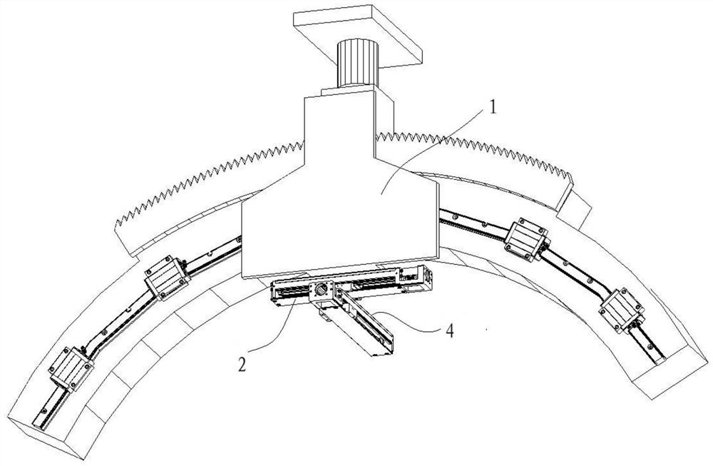
[0031] like figure 1 As shown, a coplanar mechanism for laser guidance includes a laser track device 1 and a first sliding arm and a second sliding arm arranged at the bottom of the laser track device 1. The first sliding arm includes a The first casing 2 at the bottom of the device 1 and the first slide rail mechanism arranged on the first casing 2, the first slide rail mechanism is connected with the first slider 3, the bottom of the first slider 3 and the second The second casing 4 of the sliding arm is connected, and the first sliding rail mechanism drives the second sliding arm to move left and right below the first sliding arm through a slider; the second casing 4 is provided with a second sliding rail mechanism, and the The second slide rail mechanism is connected with a second slide block 5, the bottom of the second slide block 5 is used to connect the laser emitting head, and the second slide rail mechanism drives the laser emitting head to slide in the second The bo...

Embodiment 2

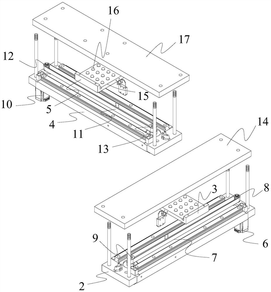
[0033] like figure 1 , figure 2 As shown, on the basis of the above embodiment, as a preferred solution, the first slide rail mechanism includes a first servo motor 6 and a first transmission belt 7, and the first servo motor 6 is vertically arranged on the At one end, the rotating shaft of the first servo motor 6 is connected with a first driving gear shaft 8, and the other end of the first housing 2 is connected with a first driven gear shaft 9, and the first driving gear shaft 8 and the first slave gear shaft 8 are connected with each other. A first transmission belt 7 is connected between the movable pinion shafts 9, and the top of the first slider 3 is connected on the first transmission belt 7; the second slide mechanism includes a second servo motor 10 and a second transmission belt 11, and the first Two servo motors 10 are vertically arranged at two ends of the second housing 4, the second driving gear shaft 12 is connected to the rotating shaft of the second servo m...

Embodiment 3

[0035] like figure 1 , figure 2 As shown, on the basis of the above embodiments, as a preferred solution, the sliding direction of the first slide rail mechanism and the sliding direction of the second slide rail mechanism are perpendicular to each other, that is, the Cartesian coordinate system of the X-axis and Y-axis constituting the plane , so that the points below the coplanar mechanism and the points coplanar with the coplanar mechanism can be marked in the Cartesian coordinate system to facilitate the positioning of the points.


PUM


Abstract

The invention belongs to the technical field of laser guidance equipment, and discloses a coplanar mechanism used for laser guidance and a control system thereof. The mechanism includes laser track equipment, and a first sliding arm and a second sliding arm arranged at the bottom of the laser track equipment, and is characterized in that the bottom of the first sliding arm is provided with a firstslide rail mechanism which is connected to the second sliding arm and drives the second sliding arm to slide relative to the first sliding arm; and the bottom of the second sliding arm is provided with a second slide rail mechanism which is used for connecting to a laser emission head and drives the laser emission head to slide relative to the second sliding arm. Plane displacement can be performed by controlling the first slide rail mechanism through a first servo motor, so that accurate positioning can be performed on angles, position adjustment can also be performed on the angles, and therefore, the positions and angles of the laser emitted by the laser emission head can be more complete; and the mechanism is smaller in size, so that moving error can be avoided, movable ranges can be more accurate, and therefore, the mechanism is more suitable for accurate adjustment of small ranges.

Description

technical field [0001] The invention belongs to the technical field of laser guiding equipment, in particular to the field of laser guiding coplanar mechanisms, in particular to a laser guiding coplanar mechanism and a control system thereof. Background technique [0002] Radioactive seed implantation treatment technology is based on the results of ultrasound, CT, MRI and other imaging examinations. First, the radioactive seed treatment planning system (Treatment Planning System, TPS) is used to accurately design the position, quantity, and implantation route of radioactive seed implantation, and formulate a treatment plan. Then, guided by CT, B-ultrasound, endoscope or percutaneous puncture under the direct vision of surgery, the radioactive particles are implanted into solid malignant tumors according to the plan through the particle implantation gun; finally, the continuous low-energy X-rays emitted by the radioactive particles Rays or γ-rays can destroy tumor tissue to t...

Claims


Application Information

Patent Timeline
Patent Type & Authority Patents(China)
IPC IPC(8): A61N5/10
CPCA61N5/1007A61N5/103A61N5/1049A61N2005/105
Inventor 王若雨曲飞寰周军王喆赵广生张翔石广越
Owner 成都真实维度科技有限公司
Why Eureka
Try Eureka