
Liquid supply device and operation method thereof

A liquid supply and liquid technology, which can be applied to devices and coatings that apply liquid to the surface. It can solve the problems of high maintenance cost, complex structure and easy wear and tear, so as to optimize the liquid supply pressure and time and accurately control the supply amount. , Supply the effect of timely response

Pending Publication Date: 2019-03-08
FAW VOLKSWAGEN AUTOMOTIVE CO LTD
View PDF11 Cites 0 Cited by
  • Summary
  • Abstract
  • Description
  • Claims
  • Application Information

AI Technical Summary

Problems solved by technology

The disadvantage is that the cylinder can only be supplied for a single supply, and the control accuracy cannot be guaranteed; therefore, it can only be used for a single model, and cannot meet the matching of different wax supplies required by multiple models.
[0004] On the other hand, the end of the valve body of the existing wax supply equipment generally has a spring leakage mechanism
However, this spring leaking structure is complex in structure, easy to wear, and is a vulnerable part, which requires frequent replacement of spare parts, high maintenance costs, and repeated filling of the supply end, resulting in delays in liquid supply and inaccurate control of supply volume

Method used


Image

  • Liquid supply device and operation method thereof
  • Liquid supply device and operation method thereof

Examples


Embodiment 1

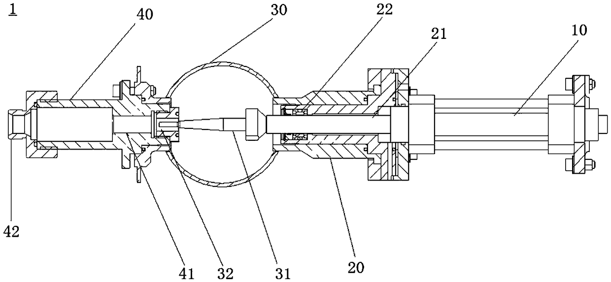
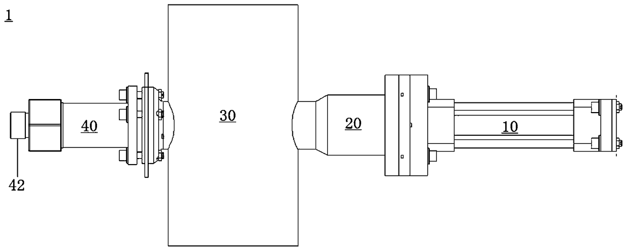
[0033] Please refer to figure 1 , 2 , is a structural diagram of a liquid supply device 1 of the present invention. Wherein, the liquid supply device 1 includes components such as a driving device 10 , a driving end sleeve 20 , a driving rod 21 , a driving end sealing element 22 , a liquid pipeline 30 , a cone valve 31 , a supply end sleeve 40 , and a supply end sealing element 41 . The liquid supply device 1 can be used, for example, as wax supply equipment in a painting workshop, but the application is not limited thereto, and the liquid supply device 1 can also be used as other liquid supply equipment.

[0034] The driving device 10 is used as a driving source to provide power to drive other components of the liquid supply device 1 . The driving device may adopt any suitable driving method, for example, it may be electric, that is, the driving device 10 may be, for example, a motor driving device. However, as the working environment of the liquid supply device 1 is diffe...

Embodiment 2

[0060] Embodiment 2 is another embodiment of the liquid supply device of the present invention. The main difference between the specific structure of Embodiment 2 and the above Embodiment 1 is that: the drive rod 21 and the drive end sleeve 20 are provided with threads. Specifically, the driving rod 21 can be a threaded screw. In Embodiment 2, the driving device 10 can perform rotational movement, and then the driving rod 21 and the cone valve 31 can be further rotated, and the driving rod 21 and the cone valve 31 can be rotated through the threads on the driving rod 21 and the driving end sleeve 20. Linear motion forward and backward to adjust the opening degree of cone valve 31.

Embodiment 3

[0062] Embodiment 3 is yet another embodiment of the liquid supply device of the present invention. In Embodiment 3, the opening degree of the cone valve 31 is determined by its rotation. Therefore, when the driving device 10 rotates, the driving rod 21 and the cone valve 31 can rotate accordingly, thereby adjusting the opening of the cone valve 31 .


PUM


Abstract

The invention discloses a liquid supply device, and further discloses an operation method of the liquid supply device. The liquid supply device comprises a driving rod, a driving device, a driving endsleeve, a liquid pipeline, a supply end sleeve, a cone valve which is positioned in the liquid pipeline, is connected with the driving rod, and extends into the supply end sleeve through an opening of the liquid pipeline, and a supply end sealing element fixed in the supply end sleeve, wherein the driving device drives the driving rod, so that multiple-opening states of the cone valve are switched. The operation method comprises the following steps that the liquid pipeline is filled with a required liquid, and negative pressure is provided or the liquid is drained; the cone valve is opened through the driving device; and the cone valve is closed through reverse driving of the driving device. According to the liquid supply device and the operation method thereof, different supply requirements of different products on liquid demand can be met through the supply device, the device is simplified, supply accuracy is improved, supply response is timely, and supply control is more accurate.

Description

technical field [0001] The present invention relates to the field of liquid supply, and more specifically relates to a liquid supply device and an operation method thereof. Background technique [0002] In the paint shop, the anti-corrosion process of the body cavity needs to inject liquid wax into the cavity of the body floor through a proprietary fixture device. According to the requirements of anti-corrosion function of the cavity of the body, for different models, and even the cavity of the bottom plate with different sizes and structures in the same model, it is necessary to inject different amounts of liquid wax. [0003] Existing wax supply equipment is driven by cylinders. The disadvantage is that the cylinder can only be supplied for a single supply, and the control accuracy cannot be guaranteed; therefore, it can only be used for a single model, and cannot meet the matching of different wax supplies required by multiple models. [0004] On the other hand, the end...

Claims


Application Information

Patent Timeline
Patent Type & Authority Applications(China)
IPC IPC(8): B05C5/02B05C11/10
CPCB05C5/02B05C11/1002B05C11/1026B05B13/06B05B1/3046
Inventor 李贤海孙桂林操金明胡炜佳
Owner FAW VOLKSWAGEN AUTOMOTIVE CO LTD
Learn More