Steel bar bending device used for building construction site

A technology of building construction and bending devices, which is applied in the field of steel bar bending devices at construction sites, can solve problems such as low bending efficiency of steel bars, unfavorable actual production, and affecting building construction efficiency, so as to achieve high bending efficiency and reduce labor costs. The effect of improving strength and bending efficiency

Pending Publication Date: 2019-03-08
THE SECOND CONSTR ENG CO LTD OF CHINA CONSTR THIRD ENG BUREAU
View PDF0 Cites 0 Cited by
  • Summary
  • Abstract
  • Description
  • Claims
  • Application Information

AI Technical Summary

Problems solved by technology

[0004] The purpose of the present invention is to provide a steel bar bending device for building construction sites, which drives the third fixed plate to move downward through the hydraulic cylinder, so that the four rollers on the third fixed plate can be processed simultaneously with four fourth fixed plates Four steel bars greatly improve the bending efficiency of steel bars, thus meeting the bending needs of building steel bars, promoting production, and solving the problem that the existing steel bar bending devices used on construction sites can only bend one steel bar at a time , which makes the bending efficiency of steel bars low, often unable to meet the actual production needs, thus affecting the construction efficiency of the building, which is not conducive to the actual production problem

Method used


Image

  • Steel bar bending device used for building construction site
  • Steel bar bending device used for building construction site
  • Steel bar bending device used for building construction site

Examples


Embodiment Construction

[0029] The following will clearly and completely describe the technical solutions in the embodiments of the present invention with reference to the accompanying drawings in the embodiments of the present invention. Obviously, the described embodiments are only some, not all, embodiments of the present invention. Based on the embodiments of the present invention, all other embodiments obtained by persons of ordinary skill in the art without creative efforts fall within the protection scope of the present invention.

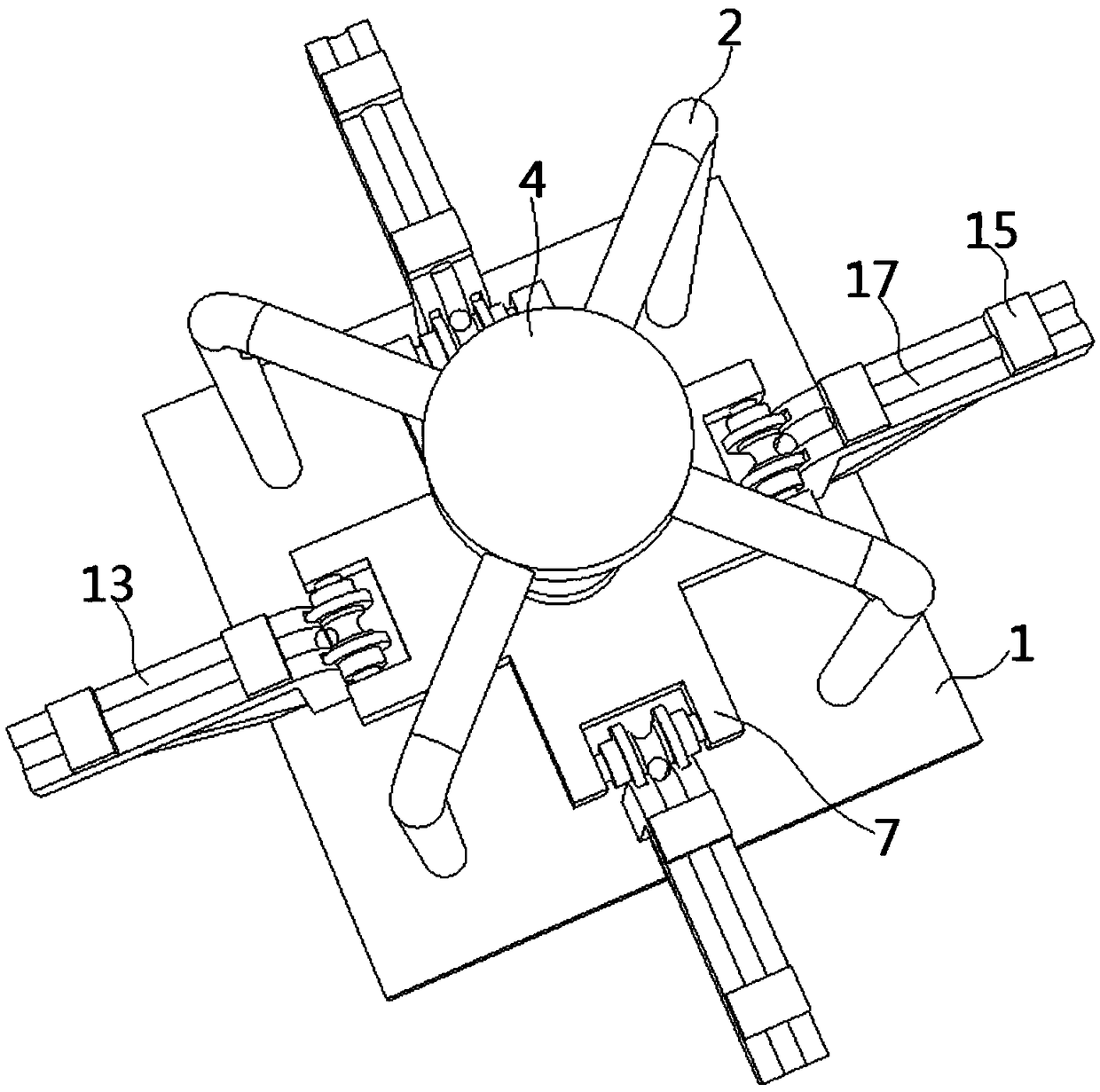
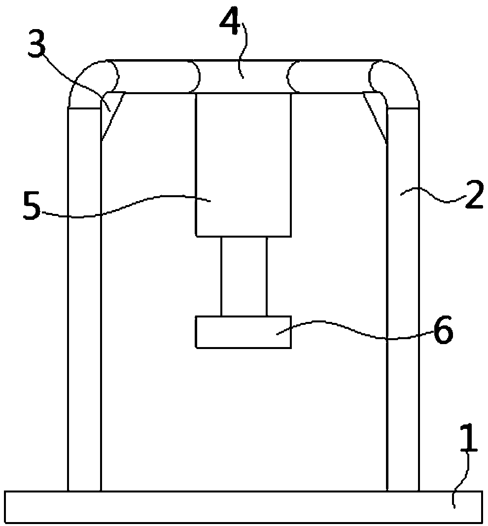
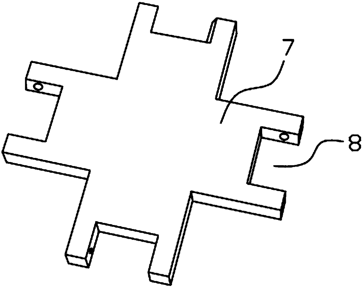
[0030] see Figure 1-7 As shown, the present invention is a steel bar bending device for a building construction site, including a base 1, a hydraulic cylinder 5, a third fixing plate 7 and a roller 9, the surface of the third fixing plate 7 is provided with a number of first A slot 8, both ends of the roller 9 are fixed with a pole 12, and the two ends of the pole 12 are rotatably connected to the inner wall of the first slot 8 through bearings, and the side of th...


PUM


Abstract

The invention discloses a steel bar bending device used for a building construction site, and relates to the technical field of steel bar processing in building construction. The steel bar bending device disclosed by the invention comprises a base, a hydraulic cylinder, a third fixing plate and rolling shafts; a plurality of slotted holes are formed in the surface of the third fixing plate; the two ends of each rolling shaft are each fixedly provided with a supporting rod; the two ends of each supporting rod are rotatably connected with the inner wall of the corresponding first slotted hole through bearings; a first bending slot is formed in the circumferential side face of each rolling shaft; a set of fixing rings is fixedly arranged at the two sides of each first bending slot; and the hydraulic cylinder is used for controlling the third fixing plate to move vertically. According to the steel bar bending device disclosed by the invention, the third fixing plate is driven by the hydraulic cylinder to move downwards, so that the rolling shafts on the third fixing plate can cooperate with fourth fixing plates to process a plurality of steel bars simultaneously, and thus, the bendingefficiency of the steel bars is greatly increased; moreover, the bent steel bars are high in strength and long in service life; labor strength is greatly reduced; and processing cost is reduced.

Description

technical field [0001] The invention belongs to the technical field of steel bar processing for building construction, and in particular relates to a steel bar bending device for a building construction site. Background technique [0002] Steel bar is one of the commonly used materials in construction now. Its use makes the building stronger and more durable. In actual use, steel bars often need to be bent to a certain extent before they can be used in building structures. However, steel bars are very special because of their characteristics. It is hard, so a special bending device is required to bend it. [0003] The existing steel bar bending device on the construction site can only bend one steel bar at a time, which makes the bending efficiency of the steel bar low and often cannot meet the actual production demand, thus affecting the construction efficiency of the building, which is not conducive to the actual At the same time, the structure of the existing steel bar b...

Claims


Application Information

Patent Timeline
IPC IPC(8): B21F1/00
CPCB21F1/00
Inventor 祝清郭伟超赵瑞明周文武杨柏松周谢萍
Owner THE SECOND CONSTR ENG CO LTD OF CHINA CONSTR THIRD ENG BUREAU
Why Eureka
Try Eureka