Fan fixing structure in outer machine for conveying refrigerants

A fixed structure and fan technology, which is used in space heating and ventilation, household heating, lighting and heating equipment, etc., can solve the problems of many fixed structural components of fans, air conditioners not equipped with dehumidification functions, and inaccurate visual adjustment. To achieve the effect of low cost, easy installation and improved strength

Pending Publication Date: 2019-03-08
ZHEJIANG XINGGUANGDIANKE SMART HOME TECH CO LTD
View PDF12 Cites 0 Cited by
  • Summary
  • Abstract
  • Description
  • Claims
  • Application Information

AI Technical Summary

Problems solved by technology

[0002] The existing indoor air environment control is generally controlled by air conditioners. Most air conditioners are equipped with dehumidification function, and some air conditioners are not equipped with dehumidification function. Some rooms are equipped with independent dehumidification equipment. The applicant uses the existing air conditioner to The principle of the air conditioner is to deliver refrigerant to the room for dehumidification and temperature control, but the fan in the existing air conditioner has many fixed structural parts, and the connection is troublesome, and the main function of the fan is to take away the heat of the heat exchanger, so the fan is relatively The location of the fan is very important, but it is troublesome to locate the positional relationship between the fan and the heat exchanger in the existing outdoor unit, and the visual adjustment is not accurate, which often affects the blowing effect

Method used


Image

  • Fan fixing structure in outer machine for conveying refrigerants
  • Fan fixing structure in outer machine for conveying refrigerants
  • Fan fixing structure in outer machine for conveying refrigerants

Examples


Embodiment 1

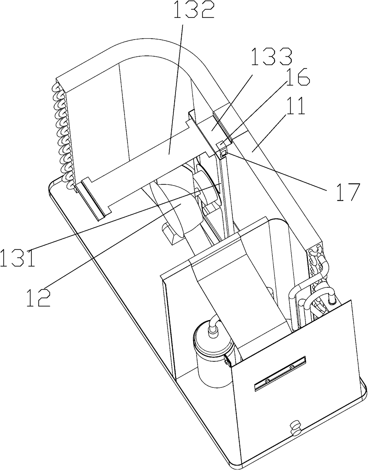
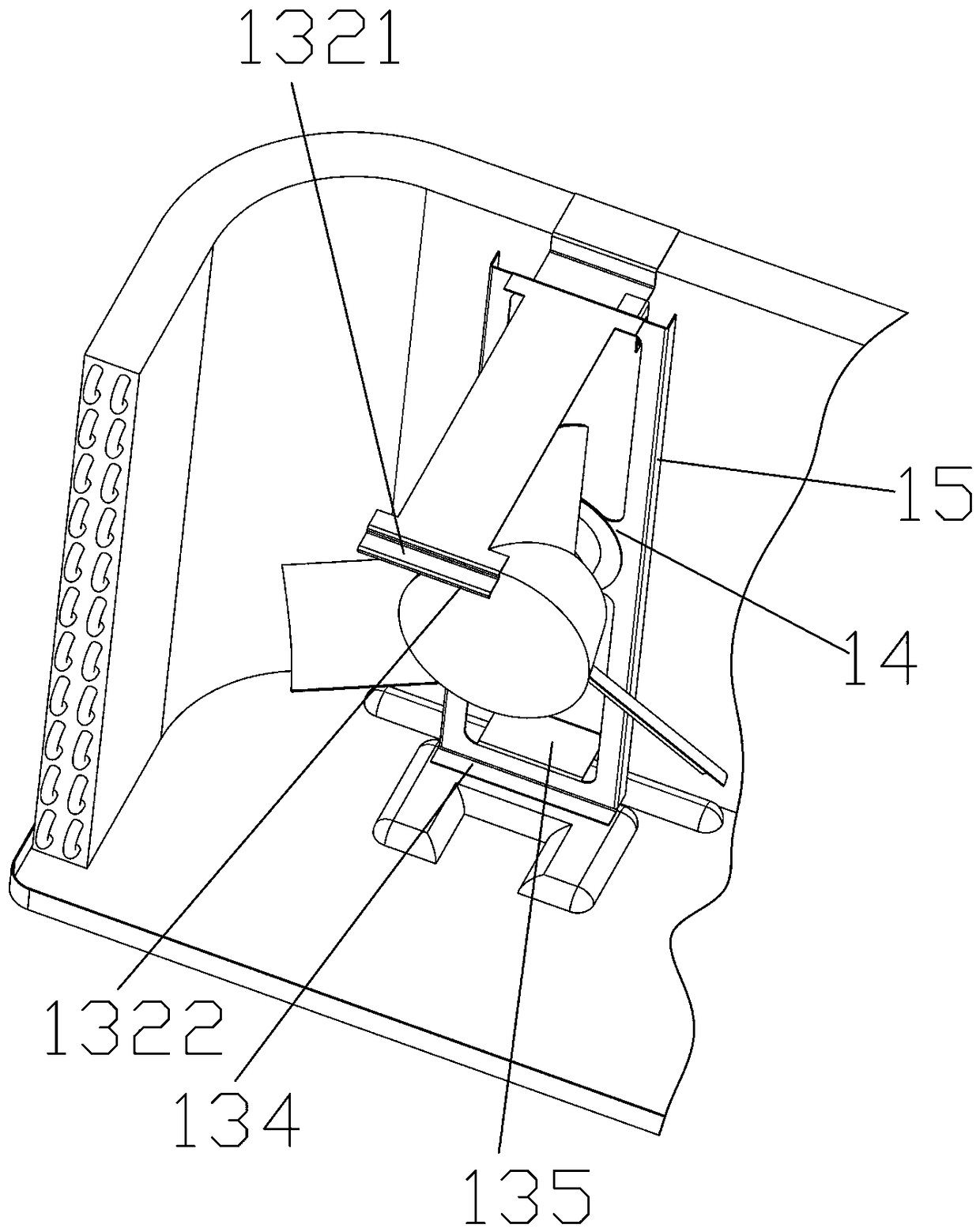
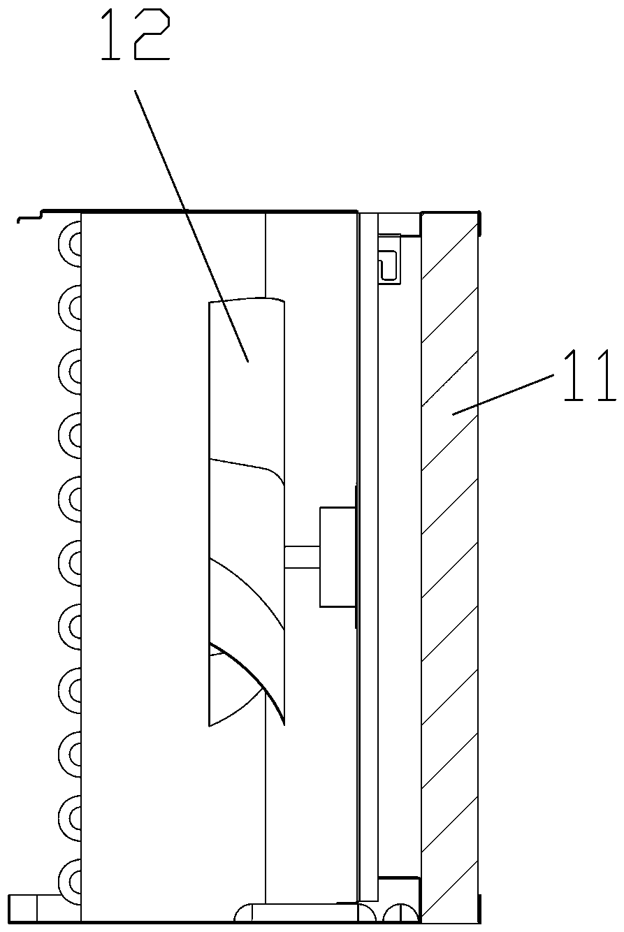
[0029] A fan fixing structure in an external machine for transporting refrigerant, wherein a heat exchanger 11, a fan 12 located inside the heat exchanger, and a fan fixing structure for fixing the fan are erected inside the outer machine, and the fan fixing structure includes The upright main frame part 131 for installing the fan and the top fixing part and the bottom fixing part respectively connected to the top and bottom of the main frame for connecting the casing of the external machine, the top fixing part includes The top inner flap 132 and the top outer flap 133 on both sides, the top inner flap and the fan are installed on the same side of the main frame part and are used to connect the top plate of the outer machine casing, the top outer flap is connected to the top outer flap The bottom fixing part includes a bottom inner flap 134 and a bottom outer flap 135, the bottom outer flap is connected to the bottom of the heat exchanger, and the bottom inner flap is connecte...

Embodiment 2

[0034] The difference from the above-mentioned embodiment is that a hanging hook piece for hanging the fan motor line is fixed on one side of the outer connecting plate section of the roof, and the hook piece includes a hook piece at the top that is welded and fixed on the outside of the roof. The hanging hook fixing plate 16 on the top surface of the connecting plate section is integrally connected to the outer edge of the hanging hook fixing plate and extends downwards with a hanging hook plate 17 .

Embodiment 3

[0036] The difference from the above-mentioned embodiment is that the connecting part of the casing is provided with an adjusting clip 18 which is partly cut out of the body of the connecting part of the casing and tilted upwards, and the bottom outer flap snaps into the adjusting clip and the The adjusting card slot 19 formed between the body of the casing connecting part. There are two adjustable clamping heads arranged symmetrically, and the outer end of the bottom outer flap is provided on the upper edge to cooperate with the adjusting clamping heads to fix the fan fixing structure along the horizontal direction parallel to the plate surface of the plate frame. The position-limited positioning notch 1343 , the adjusting clamping head fitfully presses against the two ends of the positioning notch.

[0037]The setting of the above structure can limit the fan fixing structure along the horizontal direction parallel to the plate surface of the plate frame, so as to determine t...


PUM


Abstract

The invention belongs to the field of indoor air environment regulation and control, and particularly relates to a fan fixing structure in an outer machine for conveying refrigerants. The outer machine is internally and vertically provided with a heat exchanger, a fan and a fan fixing structure, wherein the fan is located on the inner side of the heat exchanger, and the fan fixing structure is used for fixing the fan; the fan fixing structure comprises a main frame part, a top fixing part and a bottom frame part, wherein the main frame part is vertically arranged and is used for installing thefan, and the top fixing part and the bottom fixing part are connected to the top end and the bottom end of the main frame respectively and are used for connecting a shell of the outer machine; and the top fixing part comprises a top inner folding plate and a top outer folding plate which are located on the two sides of the main frame part respectively, the top inner folding plate and the fan areinstalled on the same side of the main frame part and are used for being connected to a top plate of the outer machine shell, and the top outer folding plate is connected to the heat exchanger. The structure of the application is ingeniously and integrally connected, the cost is saved while the bending is matched, and the strength is improved at the same time; and meanwhile, the fan is convenientto locate and install, the overall structure is simple, the cost is low, and the installation is convenient.

Description

technical field [0001] The invention belongs to the field of indoor air environment regulation, and in particular relates to a fan fixing structure in an external unit for conveying refrigerant. Background technique [0002] The existing indoor air environment control is generally controlled by air conditioners. Most air conditioners are equipped with dehumidification function, and some air conditioners are not equipped with dehumidification function. Some rooms are equipped with independent dehumidification equipment. The applicant uses the existing air conditioner to The principle of the air conditioner is to deliver refrigerant to the room for dehumidification and temperature control, but the fan in the existing air conditioner has many fixed structural parts, and the connection is troublesome, and the main function of the fan is to take away the heat of the heat exchanger, so the fan is relatively The location of the fan is very important, but it is troublesome to locate...

Claims


Application Information

Patent Timeline
Patent Type & Authority Applications(China)
IPC IPC(8): F24F1/38
CPCF24F1/38
Inventor 何家忠杨杰
Owner ZHEJIANG XINGGUANGDIANKE SMART HOME TECH CO LTD
Why Eureka
Try Eureka