
Automatic cleaning screw for track end face bearing

An end face bearing and automatic cleaning technology, which is applied in the field of water-cooled tube condensers and convective heat transfer enhancement, can solve the problems of small condensers that are expensive and complicated, cannot meet engineering reliability, and have insufficient automatic cleaning functions, and achieve automatic cleaning Increased strength, extended service life, and avoiding direct wear and tear

Active Publication Date: 2019-03-08
浙江建装工程技术研究有限公司
View PDF5 Cites 3 Cited by
  • Summary
  • Abstract
  • Description
  • Claims
  • Application Information

AI Technical Summary

Problems solved by technology

[0003] As we all know, the earliest success is the rubber ball cleaning device, which has significant advantages for large heat exchangers such as condensers for power plant steam turbines. However, it is too expensive and complicated for hundreds of small condensers in the petrochemical industry. Difficult to promote and apply
[0004] Self-rotating cleaning steel wire spiral cleaning technology (experimental research on automatic rotating spiral heat transfer technology, Chemical Equipment Technology, 1997, No. 5) has a simple structure and low resistance, but there are serious defects in the inner wall of the wear tube, which cannot meet the engineering reliability. basic requirements
[0005] 2014.10.15 authorized invention patent ZL201110211151.8 "A Hydrodynamic Elastic Deformation Energy Storage Self-rotating Steel Wire Spiral", which better solves the problem of the self-rotating steel wire spiral on the inner wall of the heat exchange tube. However, because most of the time it does not rotate, There is a big problem that the automatic cleaning function is insufficient

Method used

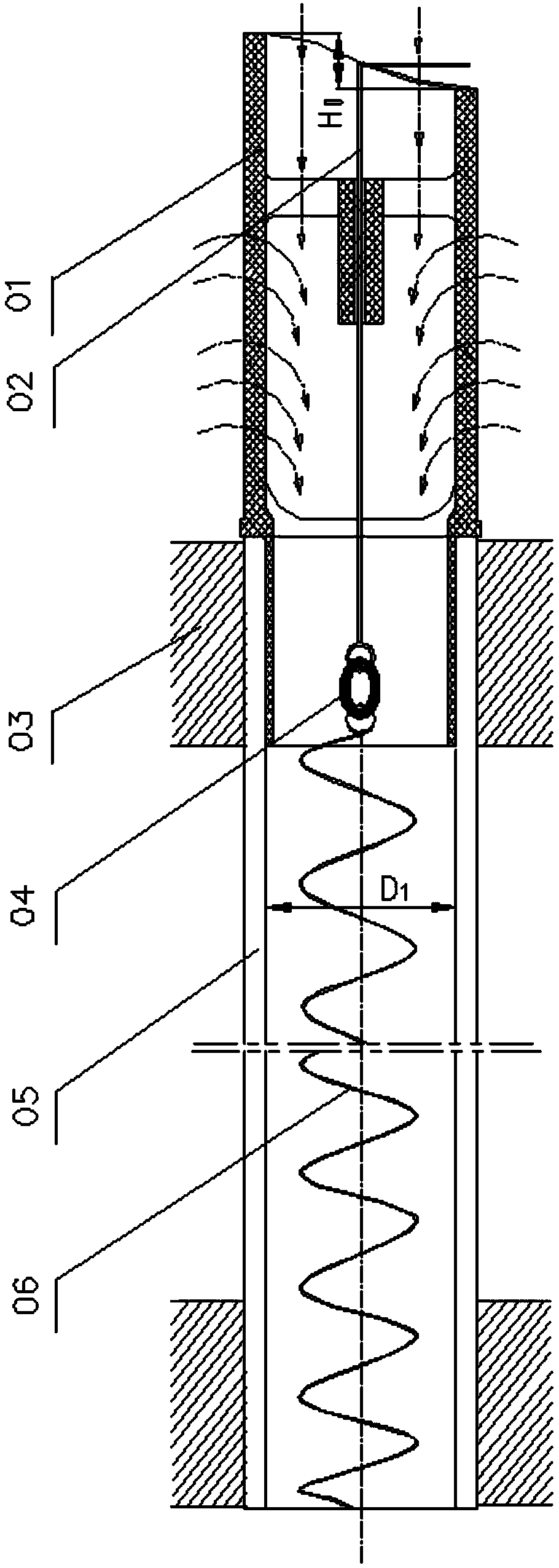
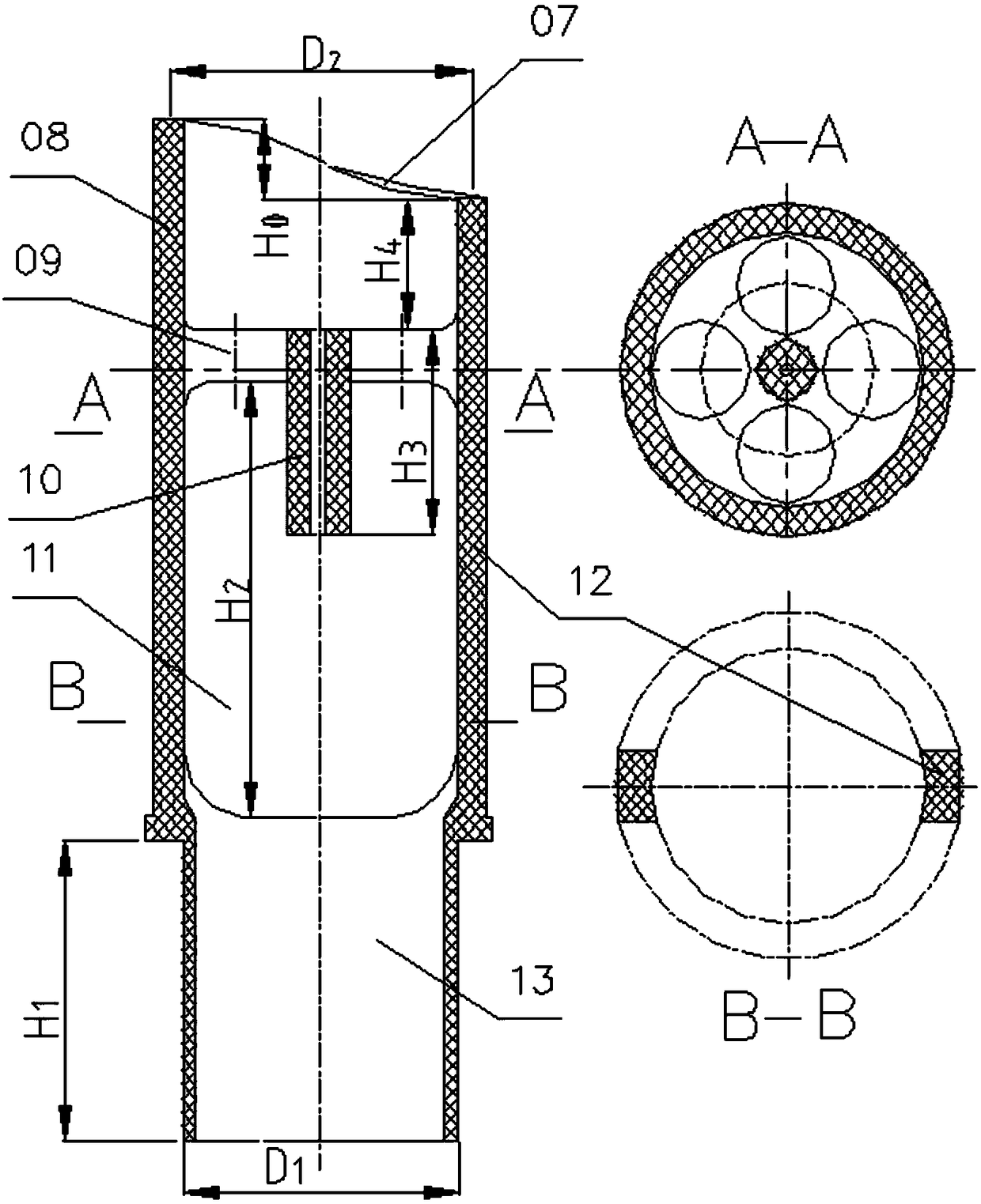
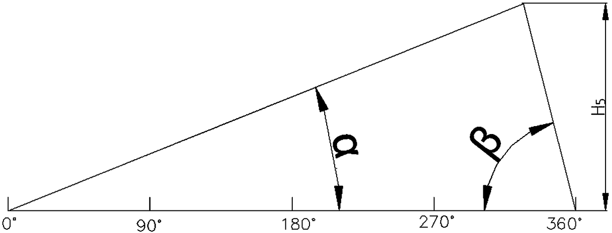

Image

  • Automatic cleaning screw for track end face bearing
  • Automatic cleaning screw for track end face bearing
  • Automatic cleaning screw for track end face bearing

Examples


Embodiment Construction

[0016] Attached below figure 1 , figure 2 , image 3 , the present invention is described in further detail.

[0017] In the figure: 1 nozzle bearing 2 hook head shaft 3 tube plate 4 plastic ring 5 heat exchange tube 6 cleaning screw 7 track end face 8 track end face bearing 9 flow hole 10 positioning bearing tube 11 inlet window 12 rib plate 13 socket tube

[0018] An automatic cleaning screw for rail end bearings, the main structural parts of which include a nozzle bearing 1, a hook shaft 2, a cleaning screw 6, and a heat exchange tube 5.

[0019] The nozzle bearing 1 is installed at the inlet end of the heat exchange tube 5 . The nozzle bearing 1 is produced by injection molding of wear-resistant engineering plastics.

[0020] After the hook shaft 2 passes through the wear-resistant plastic ring 4, it is connected with the cleaning screw 6 to avoid direct abrasion between the steel wire of the hook shaft 2 and the steel wire of the cleaning screw 6, and greatly prolong...


PUM

PropertyMeasurementUnit
Diameteraaaaaaaaaa

Abstract

The invention relates to an automatic cleaning screw for a track end face bearing. A hook head shaft moving together with the cleaning screw enables the cleaning screw to generate axial reciprocatingcleaning screw movement under the action of the track end face of a nozzle bearing, and simultaneously achieves slow rotation required for avoiding abrasion, so that the automatic cleaning capabilityof dirt is improved, and the uniformity of dirt cleaning is remarkably improved. Under the action of a positioning bearing tube, the hook head shaft can maintain coaxiality with the center line of a heat exchange tube when rotating, so that the possibility of abrasion between the cleaning screw near a pipe orifice and the inner wall of the heat exchange tube caused by rotating and shaking of the hook head shaft is avoided. The nozzle bearing is produced by injection molding of abrasion-resistant engineering plastics; and therefore, the track end face bearing has automatic spiral cleaning, simple structure, little resistance, convenient manufacture and good universality, and is suitable for tubular condenser, evaporator and crystallizer where tube pass feed liquid can generate dirt.

Description

technical field [0001] The invention relates to an automatic cleaning screw for rail end bearings, which relates to online continuous automatic cleaning of liquid dirt on the inner wall of a heat exchange tube and enhancement of convective heat transfer inside the heat exchange tube. It is generally used in shell and tube condensers, evaporators and crystallizers where the tube-side feed liquid will produce soft and hard scales. It is especially suitable for large and small water-cooled shell and tube condensers in the petrochemical industry. Background technique [0002] There are many technologies for online continuous automatic cleaning of liquid dirt on the inner wall of heat exchange tubes. [0003] As we all know, the earliest success is the rubber ball cleaning device, which has significant advantages for large heat exchangers such as condensers for power plant steam turbines. However, it is too expensive and complicated for hundreds of small condensers in the petroch...

Claims


Application Information

Patent Timeline
IPC IPC(8): F28G3/00F28G15/00F28F13/12
CPCF28F13/12F28G3/00F28G15/00
Inventor 俞天翔俞天兰彭德其彭雪松张志坤俞秀明吴金香冯修燕
Owner 浙江建装工程技术研究有限公司
Learn More