A cloth pilling tester

A tester and cloth technology, applied in the field of cloth pilling tester, can solve the problems of waste of manpower, easy displacement of cloth, and difficulty in maintaining consistent grinding force.

Active Publication Date: 2021-05-14
佛山市顺德区宁冠服装有限公司
View PDF12 Cites 0 Cited by
  • Summary
  • Abstract
  • Description
  • Claims
  • Application Information

AI Technical Summary

Problems solved by technology

[0002] Cloth is a commonly used material in decorative materials, including chemical fiber carpets, non-woven wall coverings, linen cloth, nylon cloth, colored tape, flannel, etc. In order to judge the quality of the cloth, it is necessary to conduct a pilling test on the cloth. Nowadays, the fabric is usually placed directly on the table, and then the staff continuously polishes the fabric and conducts a pilling test on the fabric. In this way, it is difficult to maintain a consistent grinding force, which leads to inaccurate test data and the fabric is easy to shift. Therefore, other staff are required to press the two ends of the fabric, which is a waste of manpower

Method used


Image

  • A cloth pilling tester
  • A cloth pilling tester
  • A cloth pilling tester

Examples


Embodiment 1

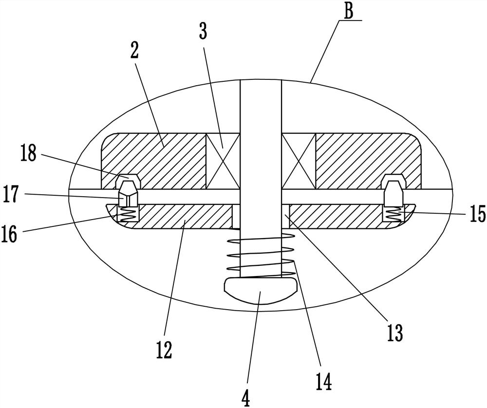
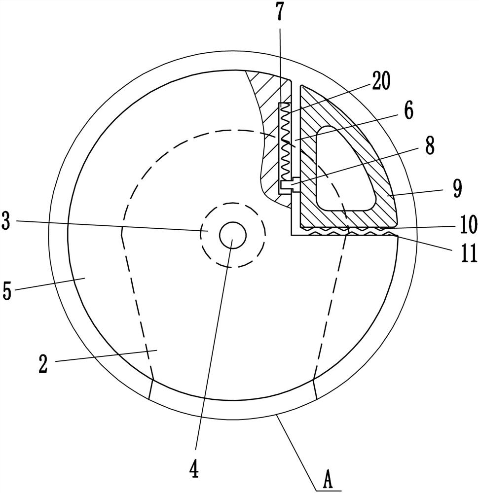
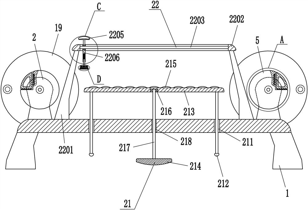
[0022] A fabric pilling tester such as Figure 1-6As shown, it includes a base 1, a mounting plate 2, a first bearing seat 3, a rotating shaft 4, a roller 5, a slider 8, a pressure plate 9, an upper tooth block 10, a lower tooth block 11, a disc 12, a first spring 14, The second spring 16, the ratchet 17, the rotating disk 19 and the third spring 20, the left and right sides of the top of the base 1 are symmetrically fixed with two mounting plates 2, and the mounting plate 2 tops on the left and right sides are embedded with the first A bearing seat 3, a T-shaped rotating shaft 4 is fixedly connected between the two first bearing seats 3 on the left side, and a T-shaped rotating shaft is also fixedly connected between the two first bearing seats 3 on the right side 4. The rollers 5 are fixedly fitted on the two rotating shafts 4, the left upper part of the left roller 5 and the right upper part of the right roller 5 are provided with installation grooves 6, and the right and r...

Embodiment 2

[0024] A fabric pilling tester such as Figure 1-6 As shown, it includes a base 1, a mounting plate 2, a first bearing seat 3, a rotating shaft 4, a roller 5, a slider 8, a pressure plate 9, an upper tooth block 10, a lower tooth block 11, a disc 12, a first spring 14, The second spring 16, the ratchet 17, the rotating disk 19 and the third spring 20, the left and right sides of the top of the base 1 are symmetrically fixed with two mounting plates 2, and the mounting plate 2 tops on the left and right sides are embedded with the first A bearing seat 3, a T-shaped rotating shaft 4 is fixedly connected between the two first bearing seats 3 on the left side, and a T-shaped rotating shaft is also fixedly connected between the two first bearing seats 3 on the right side 4. The rollers 5 are fixedly fitted on the two rotating shafts 4, the left upper part of the left roller 5 and the right upper part of the right roller 5 are provided with installation grooves 6, and the right and ...

Embodiment 3

[0027] A fabric pilling tester such as Figure 1-6 As shown, it includes a base 1, a mounting plate 2, a first bearing seat 3, a rotating shaft 4, a roller 5, a slider 8, a pressure plate 9, an upper tooth block 10, a lower tooth block 11, a disc 12, a first spring 14, The second spring 16, the ratchet 17, the rotating disk 19 and the third spring 20, the left and right sides of the top of the base 1 are symmetrically fixed with two mounting plates 2, and the mounting plate 2 tops on the left and right sides are embedded with the first A bearing seat 3, a T-shaped rotating shaft 4 is fixedly connected between the two first bearing seats 3 on the left side, and a T-shaped rotating shaft is also fixedly connected between the two first bearing seats 3 on the right side 4. The rollers 5 are fixedly fitted on the two rotating shafts 4, the left upper part of the left roller 5 and the right upper part of the right roller 5 are provided with installation grooves 6, and the right and ...


PUM


Abstract

The invention relates to a tester, in particular to a fabric pilling tester. The technical problem is: to provide a cloth pilling tester which has relatively accurate test data and can avoid cloth displacement. The technical solution of the present invention is: a cloth pilling tester, including a base, a mounting plate, a first bearing seat, a rotating shaft, a roller, a slider, a pressing plate, an upper tooth block, a lower tooth block, a disc, and a first spring , the second spring, ratchet, etc.; two mounting plates are fixed symmetrically on the left and right sides of the top of the base, and the upper parts of the mounting plates on the left and right sides are embedded with the first bearing seat, and the two first bearing seats on the left A T-shaped rotating shaft is fixedly connected between the bearing seats. The invention can tighten the cloth by rotating the right drum clockwise and the left drum counterclockwise to avoid cloth displacement; the cloth can be tightened by the tensioning mechanism, so that the staff can better adjust the cloth for sanding.

Description

technical field [0001] The invention relates to a tester, in particular to a fabric pilling tester. Background technique [0002] Cloth is a commonly used material in decorative materials, including chemical fiber carpets, non-woven wall coverings, linen cloth, nylon cloth, colored tape, flannel, etc. In order to judge the quality of the cloth, it is necessary to conduct a pilling test on the cloth. Nowadays, the fabric is usually placed directly on the table, and then the staff continuously polishes the fabric and conducts a pilling test on the fabric. In this way, it is difficult to maintain a consistent grinding force, which leads to inaccurate test data and the fabric is easy to shift. Therefore, other staff members are required to press the two ends of the fabric, which is a waste of manpower. Contents of the invention [0003] In order to overcome the shortcomings of placing the fabric directly on the table, and then the staff continuously polish the fabric, and con...

Claims


Application Information

Patent Timeline
Patent Type & Authority Patents(China)
IPC IPC(8): G01N3/56G01N3/02
CPCG01N3/02G01N3/56G01N2203/028
Inventor 彭凤娟
Owner 佛山市顺德区宁冠服装有限公司
Why Eureka
Try Eureka