
Portable power detection device

A technology of power detection and box, which is applied in the direction of measuring devices, measuring device casings, measuring electricity, etc., can solve the problems of reduced work efficiency of staff, inconvenient movement of power detection equipment, and inability to pick and place at will, so as to improve handling efficiency, The effect of facilitating the detection process and saving detection time

Pending Publication Date: 2019-03-08
SOUTHERN XINJIANG ELECTRICITY SUPPLY COMPANY OF STATE GRID XINJIANG ELECTRIC POWER +1
View PDF7 Cites 0 Cited by
  • Summary
  • Abstract
  • Description
  • Claims
  • Application Information

AI Technical Summary

Problems solved by technology

[0003] The present invention provides a portable electric power detection device, which overcomes the deficiencies of the above-mentioned prior art, and can effectively solve the problem that the existing electric power detection equipment is not easy to move, and only relies on hand-carrying, resulting in reduced working efficiency of staff and disordered detection equipment. The problem of not being able to take and put at will

Method used


Image

  • Portable power detection device
  • Portable power detection device
  • Portable power detection device

Examples


Embodiment 1

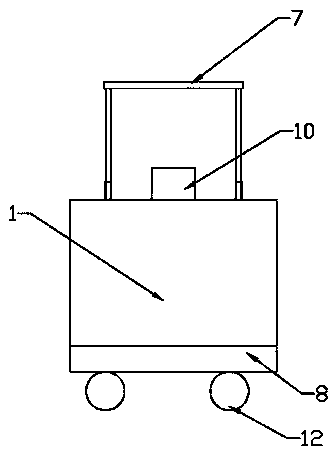
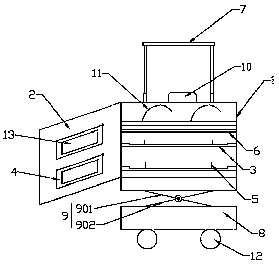
[0023] Such as Figure 1-2 As shown, the present embodiment provides a portable power detection device, comprising: a box body 1, a box door 2 is hinged at the front of the box body 1; a plurality of first support plates 3 arranged in parallel, each A support plate 3 is sequentially arranged in the box body 1 from top to bottom; preferably, the first support plate 3 is provided with a plurality of partition plates 5 perpendicular to it, for realizing the classification of testing instruments Placement; the fixing part 11, the fixing part 11 is arranged on the first support plate 3 closest to the top wall of the box body 1, and is used to fix the detection piece placed on the first support plate 3; in one embodiment of the present embodiment In a specific embodiment, the two ends of the first support plate 3 closest to the top wall of the box body 1 in the same direction are provided with fixing holes (not shown in the figure); the fixing member 11 is a fixing rope, The two en...

Embodiment 2

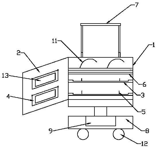
[0027] Such as image 3As shown, the difference between this embodiment and Embodiment 1 is that: the base 8 is a cavity structure with an opening at the top; The opening through the top of the base 8 is connected to the bottom wall of the box body 1; the portable power detection device also includes a control button, the control button is located on the box door 2, and its output end is connected to the hydraulic cylinder The control terminal is connected to control the hydraulic cylinder. To sum up: the portable electric power detection device of the present invention realizes drag-and-pull transportation by setting a base at the bottom of the box, and setting universal rollers at the bottom of the base, and cooperating with the push-pull assembly on the side wall of the box. , while greatly improving the handling efficiency, the workload of electric workers and the physical strength requirements of electric workers are reduced; at the same time, in the present invention, a...


PUM


Abstract

The invention belongs to the power detection technology field and discloses a portable power detection device. The device comprises a box body, a plurality of first support plates which are arranged in parallel, a fixing component, a moving plate and a plurality of second support plates, wherein the front portion of the box body is hinged to a box door; the first support plates are successively arranged in the box body from top to bottom; the fixing component is arranged on the first support plate which is closest to the top wall of the box body and is used for fixing a detection component arranged on the first support plate; the moving plate is arranged below the first support plate which is closest to the top wall of the box body and is slidably connected to the side wall of the box body; and the end portions of the second support plates are connected to the inner wall of the box door in a 90 degree hinge joint mode. The structure is reasonable and compact. Through arranging a pedestal on the bottom of the box body and arranging a universal wheel on the bottom of the pedestal, a push and pull component arranged on the side wall of the box body is cooperated to realize drag-type carrying; and carrying efficiency is greatly increased and simultaneously the workload of an electric worker and the physical requirement of the electric worker are reduced.

Description

technical field [0001] The invention belongs to the technical field of power detection and is a portable power detection device. Background technique [0002] Electric power detection equipment refers to the equipment used for test, verification, detection and acceptance of electric power production and grid operation, which provides reliable guarantee for the safety and reliability of electric power operation. Since the power transmission, transformation and distribution equipment of the power system are often erected in the field, if a fault occurs, it is not convenient for some larger equipment to be transported in time. In this case, electric workers need to bring portable testing equipment to the testing site. . Traditional portable power testing equipment generally includes a box with handles, and various testing equipment are placed in the box. During transportation, electric workers carry the equipment by carrying the handle. It can be seen that this kind of power t...

Claims


Application Information

Patent Timeline
Patent Type & Authority Applications(China)
IPC IPC(8): G01R1/04G01R1/02G01R31/00
CPCG01R1/02G01R1/04G01R31/00
Inventor 麦麦提艾力·卡米力努尔艾力·艾麦提阿斯木江·奥布力喀斯木胡海国崔学活阿不都热依木·米吉提
Owner SOUTHERN XINJIANG ELECTRICITY SUPPLY COMPANY OF STATE GRID XINJIANG ELECTRIC POWER
Learn More