
Hot fiber stripping pliers

An optical fiber and stripping pliers technology, applied in the field of optical fiber thermal stripping pliers, can solve the problems of easily damaged optical fiber core, cumbersome operation process, time-consuming and labor-intensive, etc.

Pending Publication Date: 2019-03-08
NANJING JILONG OPTICAL COMM
View PDF4 Cites 3 Cited by
  • Summary
  • Abstract
  • Description
  • Claims
  • Application Information

AI Technical Summary

Problems solved by technology

[0002] At present, manual cold stripping is mainly used for stripping large-diameter optical fibers. The manual stripping operation process is cumbersome, time-consuming and labor-intensive. There are also a small number of tools for stripping optical fiber coatings for large-diameter optical fibers in the market, but the above-mentioned stripping tools are easy to damage. The core of the optical fiber, which affects the normal function of the optical fiber

Method used


Image

  • Hot fiber stripping pliers
  • Hot fiber stripping pliers

Examples


Embodiment Construction

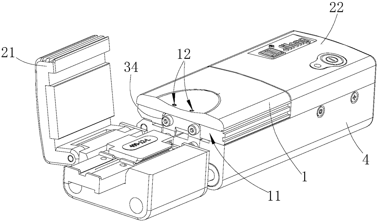
[0014] Such as Figures 1 to 2 shown

[0015] The optical fiber thermal stripper device includes a gland 1, a base 4, two clamping cover plates and a blade assembly.

[0016] The gland 1 and the two clamping covers are respectively hinged on the base 4 through pin shafts. The two clamping covers are located on both sides of the gland 1. The two clamping covers are the left clamping cover 21 and the right clamping cover respectively. Holding the cover plate 22, the lower part of the left side wall of the gland 1 has a notch 11 that matches the upper blade 31, and the notch 11 extends to the lower end surface of the cover plate. There are stripping channels for placing optical fibers.

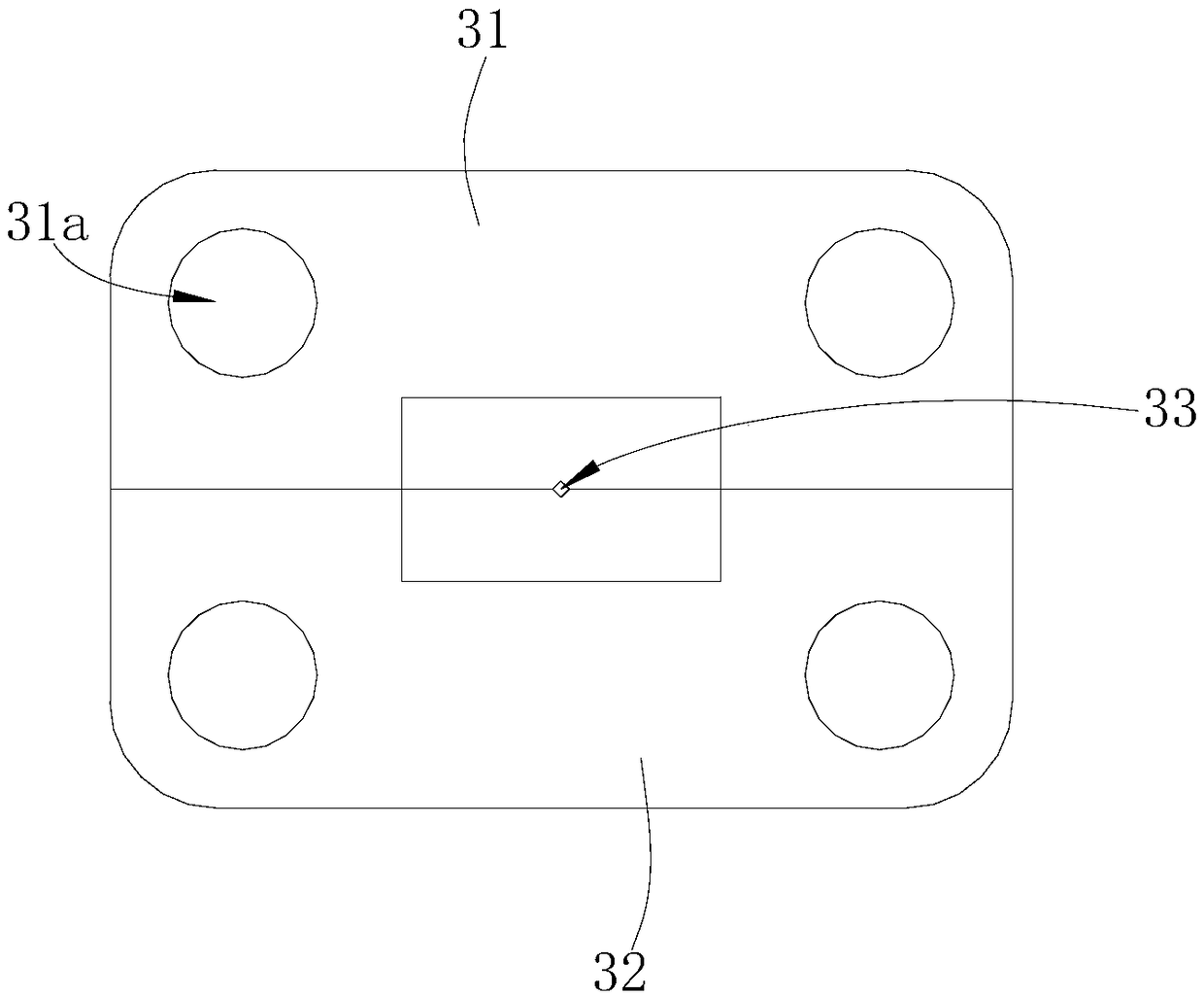
[0017] The blade assembly comprises an upper blade 31 and a lower blade 32, the lower end surface of the upper blade 31 is a cutting edge, the cutting edge of the upper blade 31 has a first V-shaped groove, and the upper blade 31 has two first through holes 31a, two The first bolts 34 pass thr...


PUM


Abstract

The invention provides hot fiber stripping pliers which include a gland, a pedestal, two clamping cover plates and a blade assembly. The gland and two clamping cover plates are hinged onto the pedestal, the clamping cover plates are positioned in the two sides of the gland respectively, and fiber stripping channels are arranged between the gland and two clamping cover plates and the pedestal; andthe blade assembly comprises upper and lower blades, the upper blade is fixedly connected to the gland, a first V-shaped groove is formed in the upper blade, the lower blade is fixedly connected to the pedestal and positionally corresponds to the upper blade, a second V-shaped groove is formed in the lower blade, and the first V-shaped groove and the upper blade and the second V-shaped groove of the lower blade form a cutting hole matching a fiber core. A fiber is placed in the wire stripping channel of the pliers, the fiber is fixed to the pedestal via the left and right clamping cover plates, the gland is pressed, a coating of the fiber is cut by cooperation of the lower and upper blades, and the fiber core is positioned in the cutting hole, and avoided from damage in the cutting process.

Description

technical field [0001] The invention relates to an optical fiber thermal stripper device. Background technique [0002] At present, manual cold stripping is mainly used for stripping large-diameter optical fibers. The manual stripping operation process is cumbersome, time-consuming and labor-intensive. There are also a small number of tools for stripping optical fiber coatings for large-diameter optical fibers in the market, but the above-mentioned stripping tools are easy to damage. The core of an optical fiber affects the normal function of the optical fiber. Contents of the invention [0003] The technical problem to be solved by the present invention is to provide an optical fiber thermal stripper device with simple structure and convenient use. [0004] In order to solve the above technical problems, the present invention provides an optical fiber thermal stripper device; [0005] Includes gland, base, two clamping covers and blade assembly; [0006] The gland and ...

Claims


Application Information

Patent Timeline
Patent Type & Authority Applications(China)
IPC IPC(8): G02B6/245
CPCG02B6/245
Inventor 张龙吴超杨炳坤
Owner NANJING JILONG OPTICAL COMM
Learn More