
A tool for crimping wire noses

A tool and nose technology, which is applied in the field of tools for crimping wire noses, can solve the problems of easy slippage, weak crimping of wires, laborious and other problems, and achieve the effect of small size, good versatility, and simple operation

Active Publication Date: 2021-10-29
STATE GRID SHANDONG ELECTRIC POWER +1
View PDF11 Cites 0 Cited by
  • Summary
  • Abstract
  • Description
  • Claims
  • Application Information

AI Technical Summary

Problems solved by technology

However, using needle-nose pliers is not only laborious, but also the crimping may not be firm due to the shape of the wire itself, and it is easy to slip off

Method used


Image

  • A tool for crimping wire noses
  • A tool for crimping wire noses
  • A tool for crimping wire noses

Examples


Embodiment 1

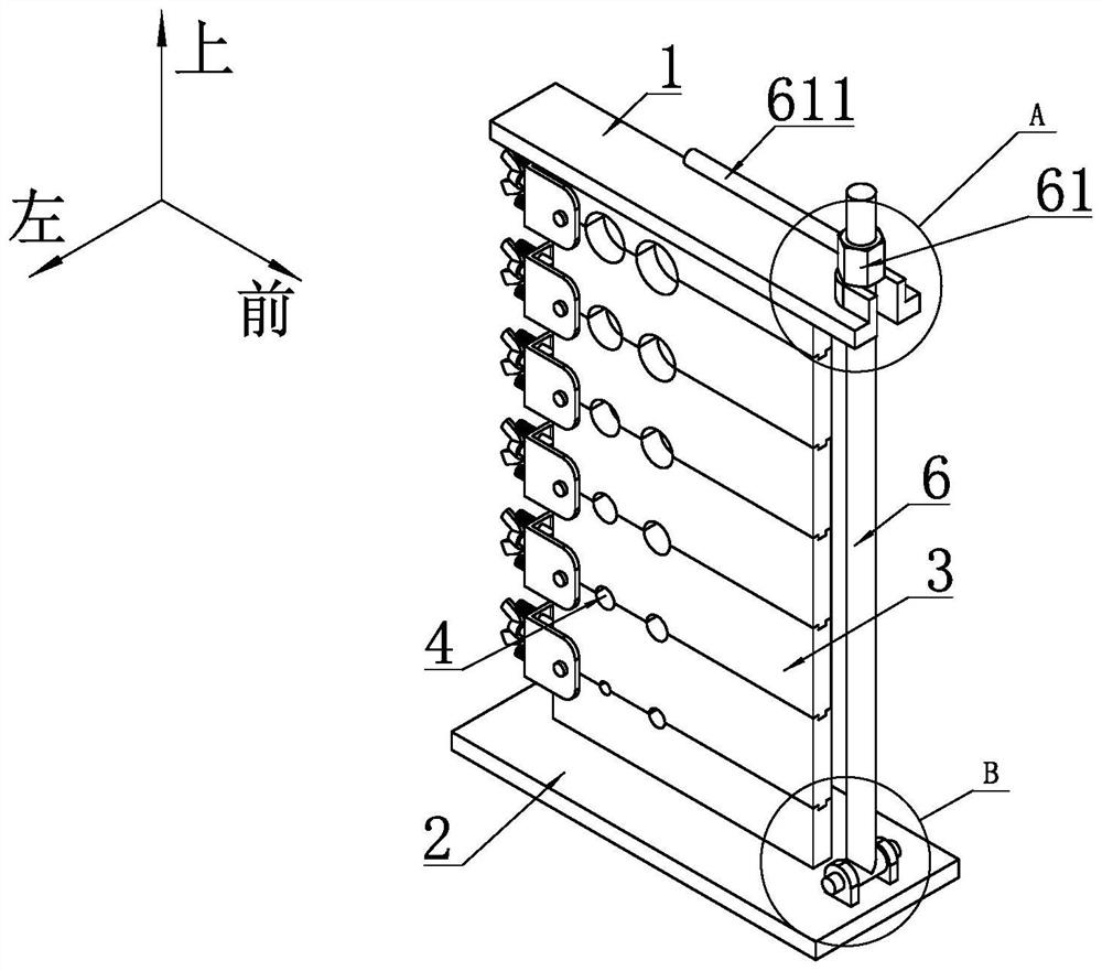
[0049] For the convenience of description, the coordinate system is defined as figure 1 , and the left-right direction is horizontal, the front-back direction is vertical, and the up-down direction is vertical.

[0050] Such as figure 1 , Figure 4 with Image 6 As shown, a tool for crimping wire lugs includes an upper clamping plate 1 and a lower clamping plate 2 arranged in parallel. As a specific embodiment, the upper clamping plate 1 and the lower clamping plate described in this embodiment 2 are rectangular, and the projections of the geometric centers of the upper clamping plate 1 and the lower clamping plate 2 in the horizontal plane are coincident, and the sides along the length direction of the upper clamping plate 1 and the lower clamping plate The sides along the length direction of 2 are parallel.

[0051] Between the upper clamping plate 1 and the lower clamping plate 2, a plurality of rectangular pressing plates 3 are arranged in the vertical direction, and t...

Embodiment 2

[0067] Such as Figure 17 As shown, the limiting mechanism includes a U-shaped bar 8 arranged between two adjacent pressing plates 3, and the front side of the pressing plate 3 is provided with an insertion hole matched with the U-shaped bar 8 . Preferably, two adjacent wing bars of two adjacent U-shaped bars 8 correspond to different sockets respectively, that is, two sockets are arranged on the front side of the pressing plate 3 located in the middle part, and the socket on the upper side is connected to the socket on the upper side. The lower side wing bar of the U-shaped bar 8 on the side is matched, and the socket positioned at the lower side is matched with the upper side wing bar of the U-shaped bar 8 positioned at the lower side.

[0068] All the other structures are the same as in Embodiment 1.


PUM


Abstract

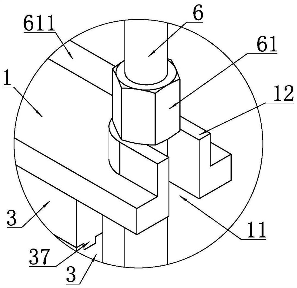
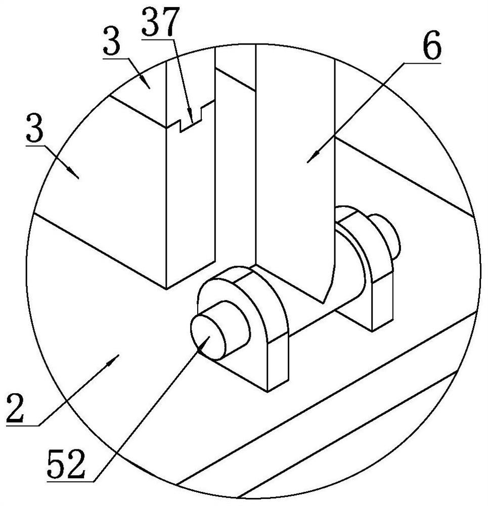
The invention discloses a tool for crimping wire lugs and relates to the technical field of electric construction equipment. The tool comprises an upper clamping plate and a lower clamping plate, and a plurality of pressing plates are stacked vertically between the upper clamping plate and the lower clamping plate. The two adjacent pressing plates are hinged by the first hinge shaft, and the pressing plates are provided with grooves. When the two adjacent pressing plates are in the closed state, the grooves on the adjacent two pressing plates jointly form a complete crimp holes. Between the upper clamping plate and the lower clamping plate, a tension rod is arranged on the front side of the pressure plate, the lower end of the tension rod is hinged to the lower clamping plate, and the upper clamping The front end of the plate is provided with a U-shaped notch for accommodating the tension rod, and the tension rod is provided with a locking nut. This tool not only saves labor, but also can ensure the uniformity of pressing, so that the wire and the wire lug are fastened together, and it is not easy to slip off.

Description

technical field [0001] The invention relates to the technical field of electric construction equipment, in particular to a tool for crimping wire lugs. Background technique [0002] Wire lugs are often used for cable end connection and continuation, which can make the connection between cables and electrical appliances stronger and safer. It is a commonly used component in construction, electrical equipment, electrical appliances, etc. At present, the wire lug is connected with the wire, and tools such as needle-nose pliers are used to compress the wire lug so that it is connected with the wire. However, using needle-nose pliers is not only laborious, but also the crimping may not be firm due to the shape of the wire itself, and it is easy to slip off. Contents of the invention [0003] In view of the above problems, the present invention provides a tool for crimping wire lugs, which not only saves labor, but also can ensure the uniformity of the crimping, so that the wir...

Claims


Application Information

Patent Timeline
Patent Type & Authority Patents(China)
IPC IPC(8): H01R43/048
CPCH01R43/048
Inventor 李家壮白勇李源王全杨子江韩春鹏张永青张琪张晔蒋佳音
Owner STATE GRID SHANDONG ELECTRIC POWER
Learn More