
A Floating Target Mechanism for Radiation Source

A technology of a ray source and a driving mechanism, applied in the field of X-ray imaging, can solve the problems of inability to adjust the position of the target material, pitting corrosion on the target surface, etc., and achieve the effect of solving the problem of target function failure, solving shrinkage deformation, and reducing moving friction.

Active Publication Date: 2020-08-21
CHINA ELECTRONIC TECH GRP CORP NO 38 RES INST
View PDF5 Cites 0 Cited by
  • Summary
  • Abstract
  • Description
  • Claims
  • Application Information

AI Technical Summary

Problems solved by technology

[0006] The technical problem to be solved by the present invention is that the position of the target cannot be adjusted in the prior art, and long-term bombardment of the target surface by high-energy electron beams will cause pitting on the target surface. A floating target mechanism for radiation sources is provided

Method used


Image

  • A Floating Target Mechanism for Radiation Source
  • A Floating Target Mechanism for Radiation Source
  • A Floating Target Mechanism for Radiation Source

Examples


Embodiment Construction

[0023] The following is a detailed description of the embodiments of the present invention. This embodiment is implemented on the premise of the technical solution of the present invention, and detailed implementation methods and specific operating procedures are provided, but the protection scope of the present invention is not limited to the following implementation example.

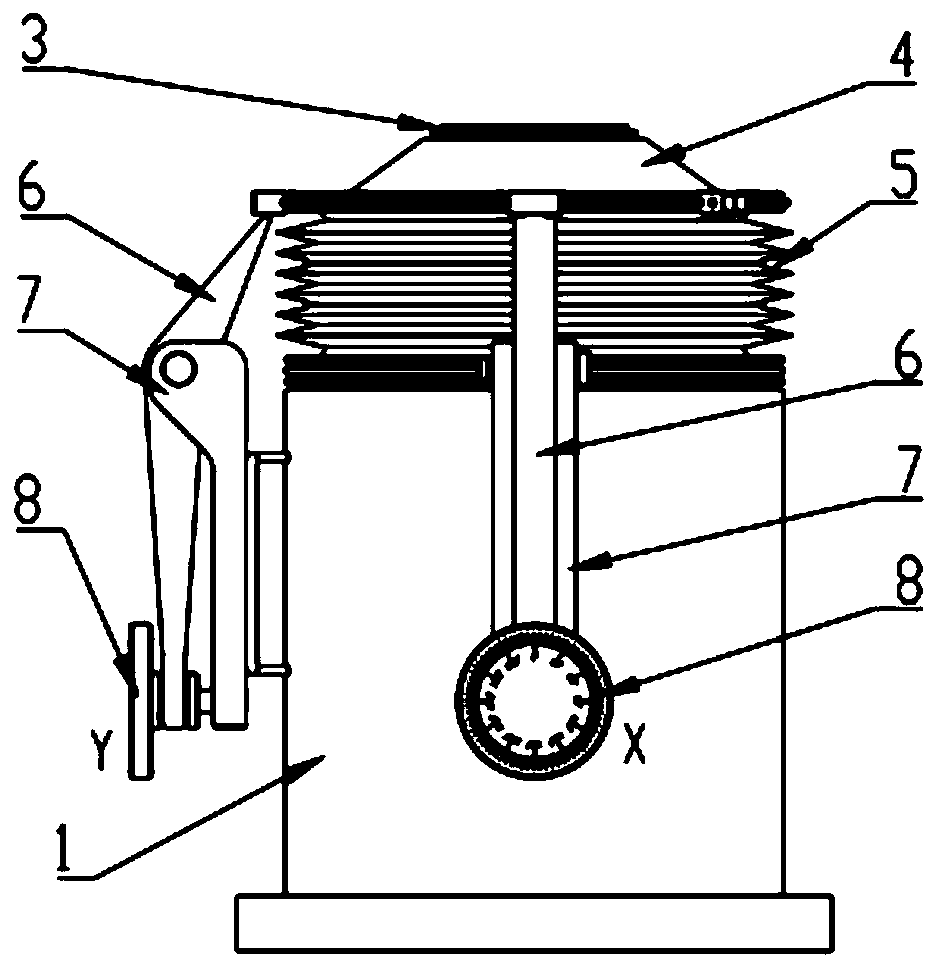
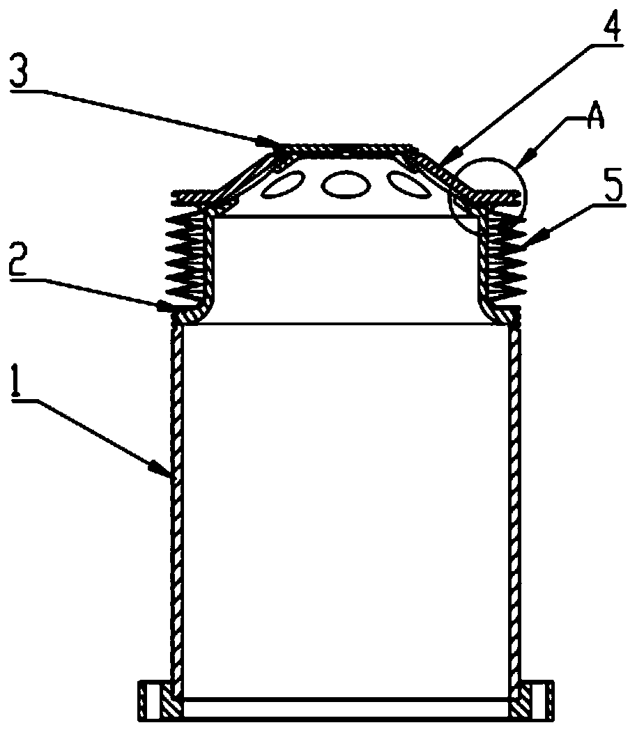
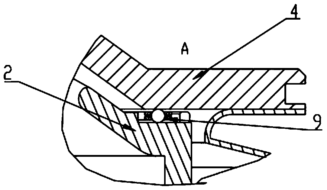
[0024] Such as Figure 1~3 As shown, this embodiment includes a radiation source housing 1, a tube shell inner cover 2, a floating target 3, a target base 4, an elastic compression tube 5 and a driving mechanism; the upper part of the target base 4 is airtightly welded to the floating target 3 The lower part of the target base 4 is airtightly welded and connected to the elastic compression tube 5, the target base 4 is located on the tube shell inner cover 2, and the lower part of the tube shell inner cover 2 is airtightly welded to the radiation source housing 1, the elastic compression tube 5 is slee...


PUM


Abstract

The invention discloses a floating target mechanism for a radiation source. The floating target mechanism comprises a radiation source shell, a pipe shell inner cover, a floating target, a target seat, an elastic compression pipe and a driving mechanism, wherein an upper part of the target seat is hermetically connected with the floating target, a lower part of the target seat is hermetically connected with the elastic compression pipe, the target seat is arranged on the pipe shell inner cover, a lower part of the pipe shell inner cover is hermetically fixed on the radiation source shell, theelastic compression pipe sleeves the pipe shell inner cover, one end of the driving mechanism is connected with the radiation source shell, and the other end of the driving mechanism is connected withthe target seat. The floating target mechanism is applied to the radiation source, the problem of target function failure caused by target surface point etching can be effectively prevented, the service lifetime of the target is substantially prolonged, and a target assembly is not needed to be replaced within the lifetime period of the radiation source.

Description

technical field [0001] The invention relates to an X-ray imaging technology, in particular to a floating target mechanism for a ray source. Background technique [0002] The X-ray source is the core component of the X-ray imaging system, which is widely used in packaging inspection, material flaw detection, medical imaging and other fields. The main function of the X-ray source is to generate X-rays. The principle is to use the electron beam generated by the internal field emission or thermionic emission of the source to bombard the window target to generate X-rays, and the generated X-rays pass through the window to radiate outside the targeted source. [0003] Conventional ray source window targets are generally made of tungsten-coated diamond sheets. X-rays are mainly produced by high-energy electron beams bombarding the tungsten coating on the diamond surface. Since the tungsten layer of the diamond window is bombarded by high-energy electron beams for a long time, it wi...

Claims


Application Information

Patent Timeline
Patent Type & Authority Patents(China)
IPC IPC(8): H01J35/24H01J35/08
CPCH01J35/08H01J35/24
Inventor 邓友银董中林姚星佳张杨
Owner CHINA ELECTRONIC TECH GRP CORP NO 38 RES INST
Learn More