Blowing device

A technology of air supply device and air supply channel, which is applied in the direction of the device for coating liquid on the surface, the arrangement of drying gas, and the dryer, etc. Problems such as the influence of degree and the effect of plate coating, etc., to achieve the effect of reducing the amount of spillage

Active Publication Date: 2019-03-12
力同环保机械(上海)有限公司
View PDF13 Cites 4 Cited by
  • Summary
  • Abstract
  • Description
  • Claims
  • Application Information

AI Technical Summary

Problems solved by technology

[0002] At present, the oven baking of the color coating production line adopts the hot air circulation method to dry the board paint in the oven. During the drying process, the temperature, wind speed, and air volume of the hot air in the oven are extremely strict. It will affect the color, reflectivity, and uniformity of color of the baked color-coated board, which will affect the use effect of the product
[0003] Because the position of the air inlet of the preset air knife is limited to the site environment, generally it can only be set on the side of the oven, but after the hot air is blown out through the air knife, the inertia of the blowing will cause the paint on the board surface to be locally heated or the board surface to be heated unevenly in the transverse direction. Make the plate reach the appropriate baking temperature and the time is different, which will affect the coating effect of the plate
Furthermore, the prior art cannot control the horizontal air output of the air knife to be the same

Method used


Image

  • Blowing device
  • Blowing device
  • Blowing device

Examples


specific Embodiment approach

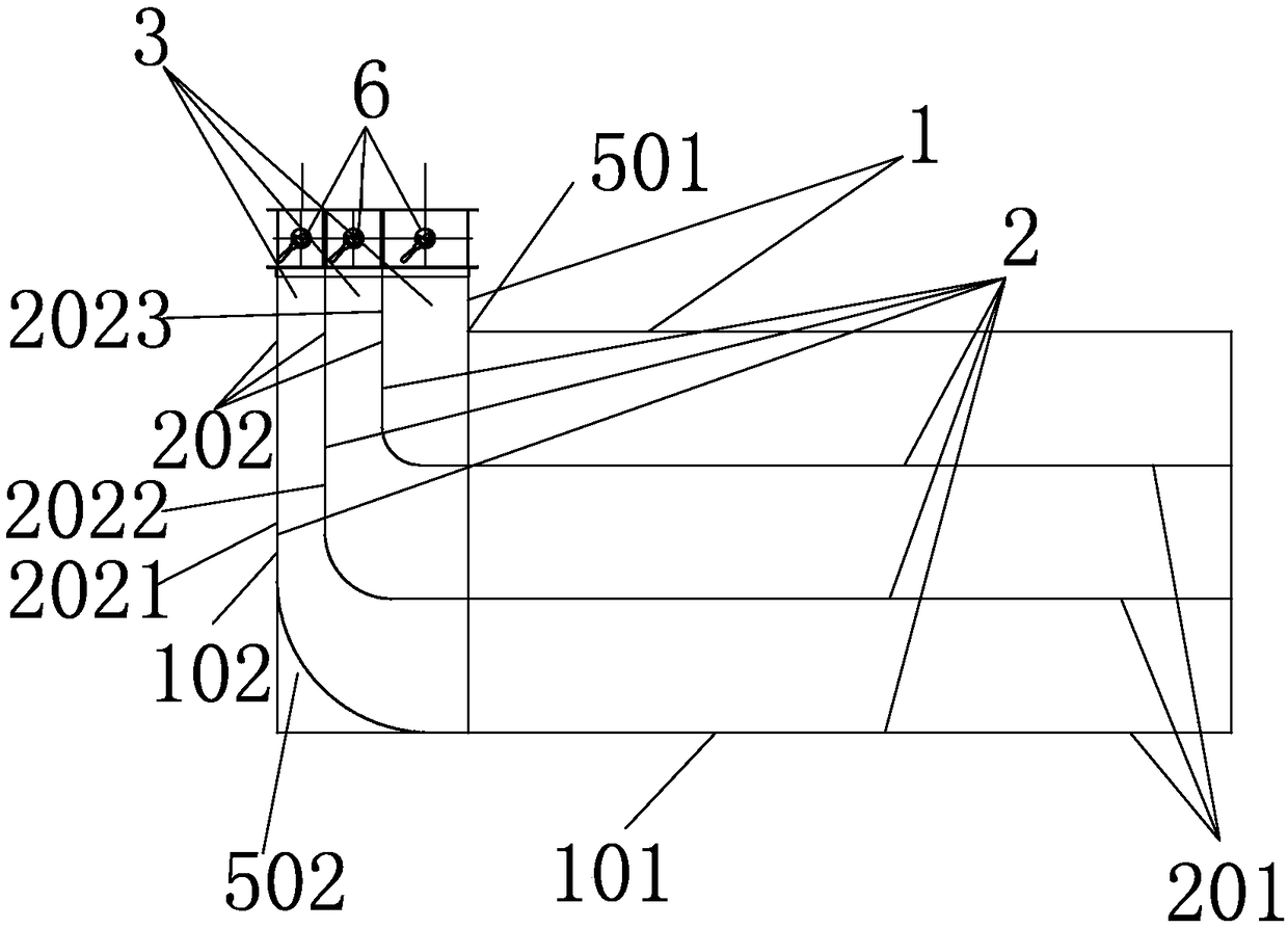
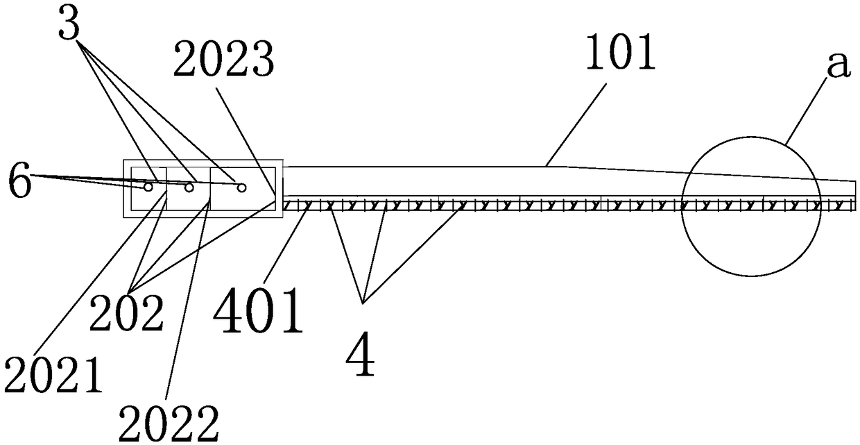
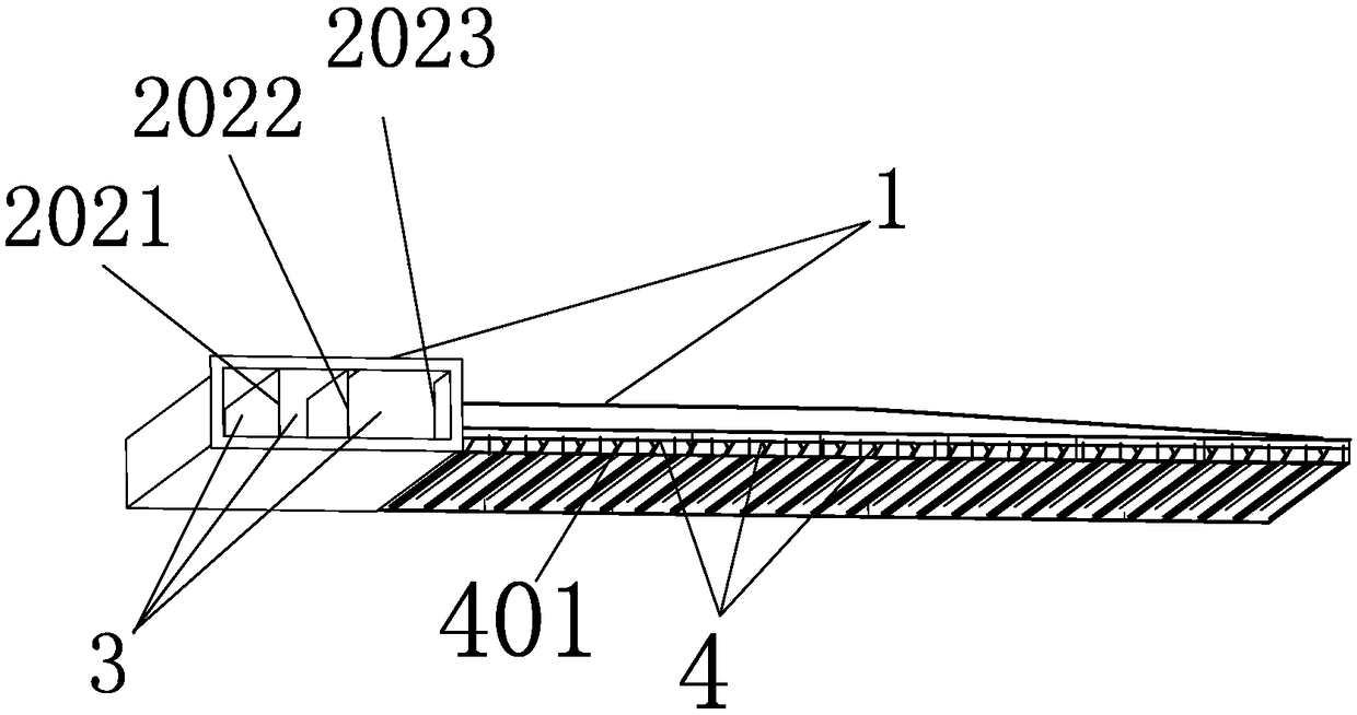
[0035] Such as Figures 1 to 4 An air supply device is shown, the air supply device is composed of a hollow L-shaped shell 1 and three L-shaped partitions 2 arranged vertically side by side in the shell, and the three L-shaped partitions 2 Divide the L-shaped shell 1 into three air inlet channels 3, the L-shaped shell 1 includes a vertical long shell 101 and a short shell 102, and the L-shaped partition 2 includes a vertical long plate 201 and a short plate 202. The lower part of the shell 101 is provided with a plurality of laterally spaced and side by side air supply knives 4, and an air supply channel 401 is formed between adjacent air supply knives 4; the bottom surface of the long shell 101 of the L-shaped shell 1 is open, and the front end of the short shell 102 is open. The remaining surfaces of the shell 1 are closed; a turn is formed between the long shell 101 and the short shell 102, the turn includes an inner turn 501 and an outer turn 502, and an arc transition is ...


PUM


Abstract

The invention discloses a blowing device which is composed of a hollow L-shaped housing and three vertically arranged L-shaped partition plates which are distributed in parallel in a spaced manner inthe housing. The three L-shaped partition plates divide the L-shaped housing into three air inlet channels. The L-shaped housing comprises a long housing and a short housing vertical to each other. Each L-shaped partition plate comprises a long plate and a short plate vertical to each other. A plurality of transverse blowing blades which are arranged in parallel in a spaced manner are arranged onthe lower part of the long housing, blowing channels are formed between adjacent blowing blades, the bottom surface of the long housing of the L-shaped housing is opened, and the front end of the short housing is opened, and other surfaces of the L-shaped housing are closed; a turn is formed between the long housing and the short housing, the turn comprises an inner turn and an outer turn, arc-shaped transition is formed between the long plate and the short plate, and the three vertically arranged short plates in parallel are parallel; and the separation distance proportion between the adjacent short edges from the inner turn to the direction, far away from the inner turn is 3: 2: 1. By changing the opening size of the air supply outlet, the air quantities of the blowing channels of the blowing device are equal.

Description

technical field [0001] The invention relates to the technical field of flat plate processing, in particular to an air supply device. Background technique [0002] At present, the oven baking of the color coating production line adopts the hot air circulation method to dry the board paint in the oven. During the drying process, the temperature, wind speed, and air volume of the hot air in the oven are extremely strict. It will affect the color, reflectivity, and uniformity of color of the baked color-coated board, which in turn will affect the use effect of the product. [0003] Since the position of the air inlet of the preset air knife is limited to the on-site environment, generally it can only be set on the side of the oven, but after the hot air is blown out through the air knife, the inertia of the blowing will cause the paint on the board surface to be locally heated or the board surface to be heated unevenly in the transverse direction. The time to make the board rea...

Claims


Application Information

Patent Timeline
Patent Type & Authority Applications(China)
IPC IPC(8): B05D3/04F26B21/00
CPCF26B21/004B05D3/0406
Inventor 曾义海张敏陈巍巍吴鑫母岩奇
Owner 力同环保机械(上海)有限公司
Why Eureka
Try Eureka