Bending die for cooling pipe in poloidal field coil support and method of bending die

A technology of coil support and cooling pipe, applied in the field of pipe bending and forming, can solve the problems of unsuitable production of small-scale pipe fittings, difficult to control the overall size and shape, and high price of CNC pipe bending machines, so as to compensate for the inconsistency of product size. Qualified, convenient for one-time molding, and the effect of improving reliability

Inactive Publication Date: 2019-03-12
GUIZHOU AEROSPACE XINLI CASTINGSAND FORGINGS
View PDF5 Cites 0 Cited by
  • Summary
  • Abstract
  • Description
  • Claims
  • Application Information

AI Technical Summary

Problems solved by technology

[0003] When using a general hydraulic pipe bender to bend the cooling pipe, one end of the pipe needs to be fixed first, and then the other end should be bent. After the first forming is completed, the fixed end needs to be loosened, and the second clamping is performed to complete the second forming. With this method, only one molding can be completed, and the product size should be measured once. During the second molding, a second clamping is required. The clamping point can only be controlled by manual measurement. There is a certain error, and many times There are cumulative errors in the measurement. The overall size and shape of the pipes bent by this method are difficult to control, and it is time-consuming; The volume control is good, but it is also limited by the space size, complexity and the total length of the pipe fittings to be bent, and the bending of the pipe fittings cannot be completed, and the CNC pipe bending machine is relatively expensive, which is not suitable for the production of pipe fittings with a small ratio From the above analysis, it can be seen that neither the hydraulic pipe bender nor the CNC pipe bender can complete the bending of the cooling pipe well.

Method used


Image

  • Bending die for cooling pipe in poloidal field coil support and method of bending die
  • Bending die for cooling pipe in poloidal field coil support and method of bending die
  • Bending die for cooling pipe in poloidal field coil support and method of bending die

Examples


Embodiment Construction

[0051] The present invention will be described in further detail below in conjunction with the accompanying drawings, but not as a basis for limiting the present invention. The following dimensions are all in millimeters.

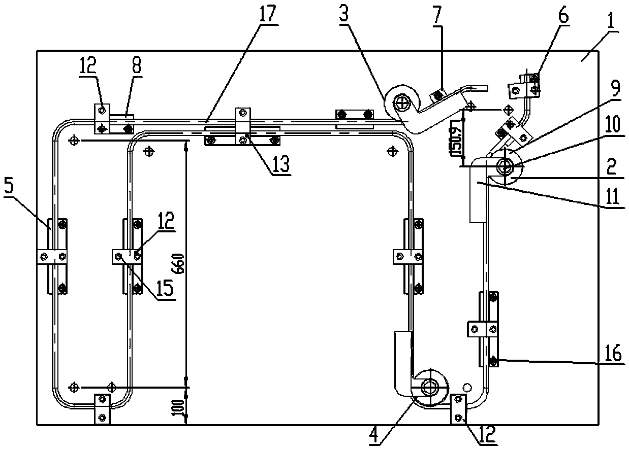
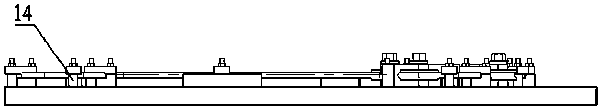
[0052] Such as figure 2 , 3 As shown, a bending die for cooling pipes supported by poloidal field coils mainly includes a curved bottom plate 1, a first bending die 2, a second bending die 3, a third bending die 4, a first baffle plate 5, a second bending die The second type of baffle 6, the third type of baffle 7, the fourth type of baffle 8, the roller 9, the positioning shaft 10, the bent handle 11, the first type of pressure plate 12, the second type of pressure plate 13, the washer 14, the screw and the nut 15 and hexagon socket head cap screws 16;

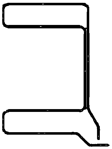
[0053] A hole for positioning the shaft 10 is placed at the position where the bending radius round point of the cooling pipe 17 is located on the curved bottom plate 1;

[0054] The first bending die 2,...


PUM


Abstract

The invention discloses a bending die for a cooling pipe in a poloidal field coil support. Positioning shaft holes are formed in cooling pipe bending radius round points arranged on a bending bottom plate. Wheels and bending handles are fixedly arranged on the bending bottom plate through positioning shafts via the holes. Stress application bars are arranged in the threaded holes of the bending handles. Four baffles are arranged on the bending bottom plate through screw rods and nuts via gaskets. Two pressing plates are arranged on the bending bottom plate through hexagon socket head cap screws. The cooling pipe drawing is carved on the bending bottom plate, the bending radius round point positions are marked, the threaded holes containing the positioning shafts are drilled and tapped at the positions, where the bending radius round points are arranged, on the bending bottom plate, threaded holes used for installing the four baffles are drilled and tapped, the threaded holes are used for fixing the three bending dies and the four baffles, then one end of the bent cooling pipe penetrates the bending handles and the wheels, and one end of the cooling pipe is fixed to the bending bottom plate. The stress application bars are arranged in the threaded holes of the bending handles, the stress application bars are rotated according to the drawing orientation of the cooling pipe, the cooling pipe and the wheels can rotate, after the cooling pipe and the wheels rotate to positions, the stress application bars are loosened, and the cooling pipe is rebounded to the bending position.

Description

technical field [0001] The invention belongs to the technical field of bending and forming of pipe fittings in the field of mechanical manufacturing, and in particular relates to a bending mold of a cooling pipe in a poloidal field coil support and a method thereof. Background technique [0002] The cooling pipe is a stainless steel (316L) pipe fitting. Both ends are welded to other pipe fittings in the poloidal field coil support. The cooling gas (inert gas) in the cooling pipe takes away heat energy and is an important part of the poloidal field coil support. The spatial shape of the pipe fitting is relatively complex and needs to be bent and formed many times. If the pipe bending machine is used, the following problems exist: [0003] When using a general hydraulic pipe bending machine to bend the cooling pipe, one end of the pipe needs to be fixed first, and the other end should be bent. After the first forming, the fixed end needs to be loosened, and the second clamping...

Claims


Application Information

Patent Timeline
Patent Type & Authority Applications(China)
IPC IPC(8): B21D7/00
Inventor 梁安玲唐海平
Owner GUIZHOU AEROSPACE XINLI CASTINGSAND FORGINGS
Why Eureka
Try Eureka