Floor split joint ventilating pipe structure and ventilating structure

A technology for ventilation pipes and floor slabs, which is applied to floors, vertical pipes, building components, etc. It can solve the problems of affecting the appearance of buildings and affecting indoor net heights, and achieves the effects of low cost, convenient disassembly, and improvement of cracks

Pending Publication Date: 2019-03-12
SANY CONSTR TECH CO LTD
View PDF0 Cites 0 Cited by
  • Summary
  • Abstract
  • Description
  • Claims
  • Application Information

AI Technical Summary

Problems solved by technology

[0004] The purpose of the present invention is to provide a floor joint ventilation pipe structure to solve the technical problems that the ventilation pipes are installed separately in the existing building ventilation structure, which affects the appearance of the building and affects the indoor net height
[0005] Another object of the present invention is to provide a ventilation structure to solve the technical problem that the ventilation pipes are arranged separately in the existing building ventilation structure, which affects the appearance of the building

Method used


Image

  • Floor split joint ventilating pipe structure and ventilating structure
  • Floor split joint ventilating pipe structure and ventilating structure
  • Floor split joint ventilating pipe structure and ventilating structure

Examples


Embodiment 1

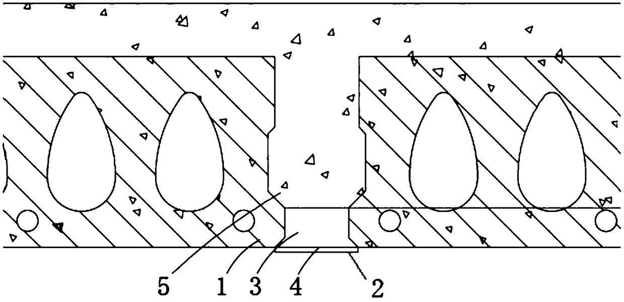
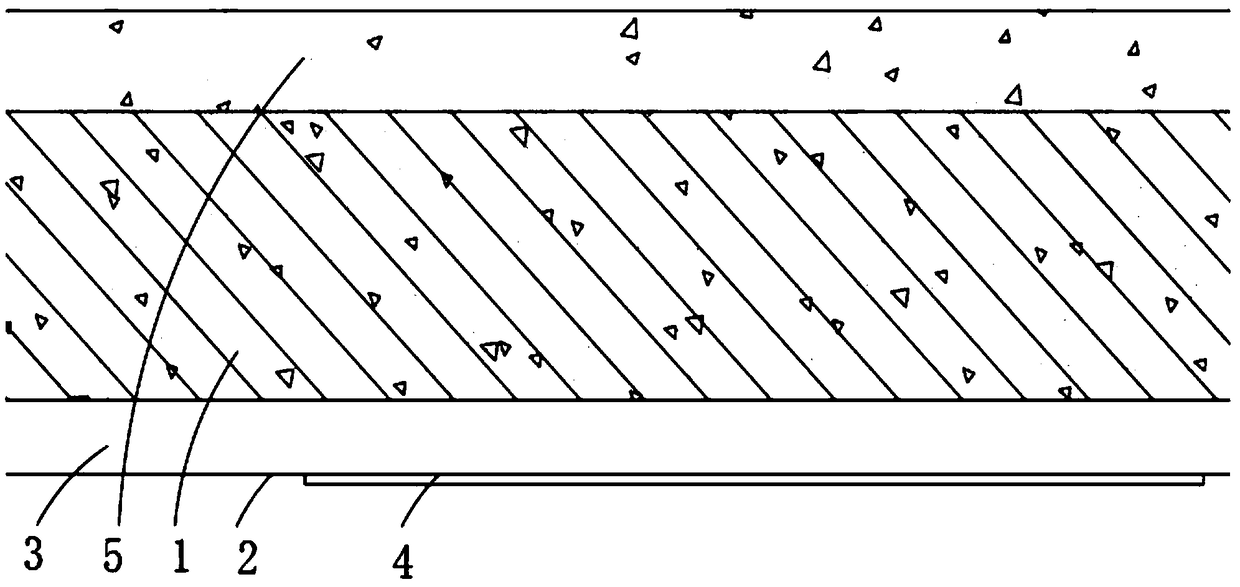
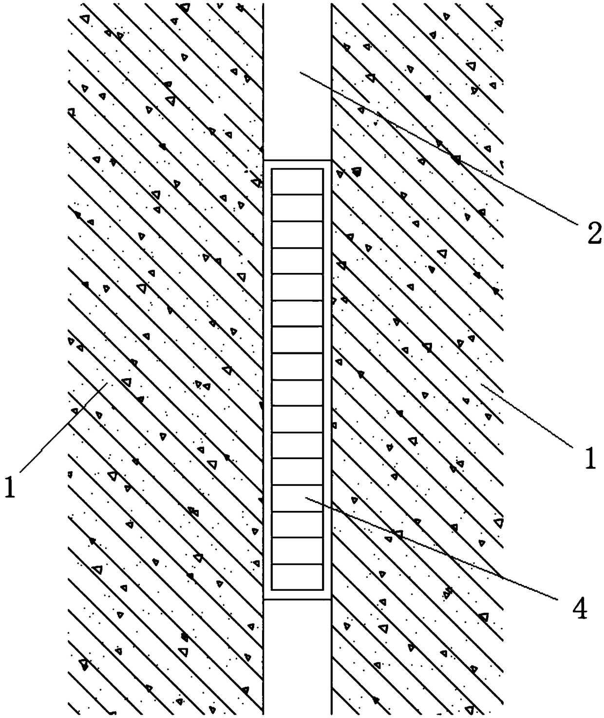
[0035] figure 1 A structural schematic view of the floor joint ventilation pipe structure provided by the embodiment of the present invention at a viewing angle; figure 2 A structural schematic view of the floor joint ventilation pipe structure provided by the embodiment of the present invention at a viewing angle; image 3 It is a structural schematic view of the joint ventilation pipe structure of the floor slab provided by the embodiment of the present invention at a viewing angle. see Figure 1-3 As shown, this embodiment provides a floor joint ventilation pipe structure, the floor joint ventilation pipe structure includes a floor, the floor is a joint floor 1, and a joint is formed between the joint floor 1, the said The lower part of the splicing seam is provided with a cover plate 2, and the cover plate 2 and the splicing seam form a ventilation groove 3;

[0036] Vents 4 are arranged on the cover plate 2 .

[0037] In this embodiment, the floor slab generally refe...

Embodiment 2

[0043] This embodiment provides a floor joint ventilation pipe structure. The floor joint ventilation pipe structure has an overall structure similar to that of Embodiment 1. The difference is that this embodiment provides a specific structure of the floor joint ventilation pipe structure.

[0044] see Figure 1-3 As shown, the floor joint ventilation pipe structure of this embodiment includes a floor, the floor is a joint floor 1, a joint is formed between the adjacent joint floors 1, and the lower part of the joint is provided with a cover plate 2 , the cover plate 2 and the seam form a ventilation groove 3;

[0045] Vents 4 are arranged on the cover plate 2 .

[0046] The spliced ​​floor slabs described in this embodiment are SP hollow prestressed slabs. The SP hollow prestressed slabs have environmental protection, energy saving, sound insulation, shock resistance, flame retardancy, good ductility of SP slabs, large deflection before failure, and high slab safety. advant...

Embodiment 3

[0054] This embodiment provides a ventilation structure, which includes the floor joint ventilation pipe structure described in Embodiment 1 or Embodiment 2.

[0055] see Figure 1-3 As shown, the floor joint ventilation pipe structure of the ventilation structure in this embodiment includes a floor, the floor is a joint floor 1, a joint is formed between the adjacent joint floor 1, and the lower part of the joint is provided with a cover plate 2, the cover plate and the seam form a ventilation groove 3;

[0056] Ventilation openings 4 are arranged on the cover plate.

[0057] The spliced ​​floor slabs described in this embodiment are SP hollow prestressed slabs. The SP hollow prestressed slabs have environmental protection, energy saving, sound insulation, shock resistance, flame retardancy, good ductility of SP slabs, large deflection before failure, and high slab safety. advantage.

[0058] Optionally, in this embodiment, the cover plate 2 is in close contact with the lo...


PUM


Abstract

The invention discloses a floor split joint ventilating pipe structure and a ventilating structure comprising the same. The floor split joint ventilating pipe structure comprises a floor, wherein thefloor is a split joint floor, a split joint is formed between adjacent split joint floors, a cover plate is arranged at the lower part of the split joint, the cover plate and the split joint form a ventilating groove, and the cover plate is provided with a ventilating port. According to the floor split joint ventilating pipe structure, the floor split joint is used as the ventilating pipe, so thatthe floor split joint ventilating pipe structure is low cost and attractive appearance, does not need suspended ceilings and the like to be used for shielding and beautifying, can improve cracks of prefabricated floor pieces, and is convenient to maintain, clean and disassemble in the later period.

Description

technical field [0001] The invention relates to a building ventilation pipe structure, in particular to a floor joint ventilation pipe structure and a ventilation structure. Background technique [0002] Building ventilation is divided into natural ventilation and mechanical ventilation. It means that the dirty air in the building is directly or purified and discharged to the outside, and then fresh air is added in, so as to keep the indoor air environment in line with hygienic standards. Its purpose: 1. To ensure the elimination of indoor pollutants 2. To ensure the thermal comfort of indoor personnel 3. To meet the needs of indoor personnel for fresh air. [0003] In today's society, the demand for indoor health and comfort in buildings is getting higher and higher. Building ventilation methods such as smog removal technology, passive house fresh air technology, and central air-conditioning technology emerge in an endless stream. However, the ventilation pipes of the exist...

Claims


Application Information

Patent Timeline
IPC IPC(8): E04B5/48E04F17/04
CPCE04B5/48E04F17/04
Inventor 陈光唐动直张雪松
Owner SANY CONSTR TECH CO LTD
Why Eureka
Try Eureka