Remote soil monitoring device

A soil monitoring and remote technology, applied in measuring devices, soil material testing, instruments, etc., can solve problems such as unfavorable agricultural development, inability to achieve real-time monitoring, inability to real-time soil monitoring, unfavorable information integration construction, etc., to maintain normal operation , the effect of high conversion rate

Pending Publication Date: 2019-03-12
INST OF AGRI RESOURCES & REGIONAL PLANNING CHINESE ACADEMY OF AGRI SCI +1
View PDF0 Cites 2 Cited by
  • Summary
  • Abstract
  • Description
  • Claims
  • Application Information

AI Technical Summary

Problems solved by technology

[0003] Most of the current soil monitoring uses samplers to regularly collect soil samples and analyze and test the soil samples. Real-time monitoring cannot be achieved. Due to the variability of the environment and the interference of human factors, the inability to monitor the soil in real time is not conducive to information integration. Construction is not conducive to the development of modern agriculture

Method used


Image

  • Remote soil monitoring device
  • Remote soil monitoring device
  • Remote soil monitoring device

Examples


Embodiment 1

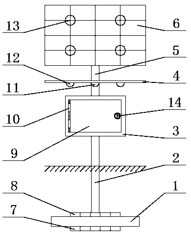
[0022] Such as Figure 1-3 The shown remote soil monitoring device includes a base 1, a fixed rod 2, an electric control box 3 and a fixed plate 4, a first sensor 7 is installed on the bottom of the base 1, and a fixed rod 2 is installed on the top of the base 1 , the second sensor 8 is installed on the outside of the fixed rod 2, and the first sensor 7 and the second sensor 8 all include a soil temperature sensor, a soil moisture sensor, a soil pH sensor, a soil salinity sensor, and a soil heavy metal sensor. The base 1 is buried in the soil for fixing, and the soil is monitored by the first sensor 7 and the second sensor 8 on the base 1, and an electric control box 3 is installed on the upper end of the fixed rod 2, and the electric control box 3 A box door 9 is installed on the top, and the box door 9 is connected to the electric control box 3 through a hinge 10. A lock 14 is installed on the box door 9, and a sealing ring is installed at the connection between the box door...

Embodiment 2

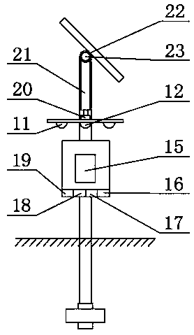
[0024] The difference between this embodiment and Embodiment 1 is that the surface of the solar cell panel 6 is equipped with a multi-directional light sensor 13, and the first reduction motor 20 is installed in the support column 5, and the first reduction motor 20 is connected to the bottom The fixed plate 4 is fixedly connected, and a rotating shaft 21 is installed on the upper end of the first geared motor 20, and a second rotating shaft 22 is installed on the top of the rotating shaft 21, and a second geared motor 23 is installed on the second rotating shaft 22. The rotating shaft 22 is fixedly connected to the solar panel 6, and the second deceleration motor 23 is fixedly connected to the support column 5. The first deceleration motor 20 cooperates with the multi-directional light sensor 13, so that the solar panel 6 faces the sun throughout the day. , improve the energy conversion efficiency, through the cooperation of the second gear motor 23 and the multi-directional l...


PUM


Abstract

The invention relates to a remote soil monitoring device, and belongs to the technical field of soil monitoring. The remote soil monitoring device comprises a base, a fixing rod, an electric control box and a fixing plate; a first sensor and a second sensor are mounted at the bottom of the base, and the electric control box and the fixing plate are mounted at the upper end of the fixing rod; a camera and an infrared imaging device are mounted at the bottom of the fixing plate, and a supporting column is mounted at the upper end of the fixing plate; and a solar cell panel with the adjustable direction is arranged at the upper end of the supporting column. Through the sensors, soil is comprehensively monitored in real time, appropriate agricultural production is conveniently conducted in time according to the soil situation, a multidirectional illumination sensor cooperates with the solar cell panel to supply power to the device, thus the solar cell panel keeps the high conversion rate,the device keeps operating normally, and the monitoring device is effectively monitored through the camera and the infrared imaging device.

Description

technical field [0001] The invention relates to the technical field of soil monitoring, in particular to a remote soil monitoring device. Background technique [0002] Soil quality is the ability of soil to maintain production within the ecosystem interface, ensure environmental quality, and promote healthy behaviors of animals and humans. Soil environmental monitoring refers to the determination of environmental quality and its changing trend through the determination of representative values ​​of factors affecting soil environmental quality , so that corresponding measures can be taken in a timely manner according to the monitoring results. [0003] Most of the current soil monitoring uses samplers to regularly collect soil samples and analyze and test the soil samples. Real-time monitoring cannot be achieved. Due to the variability of the environment and the interference of human factors, the inability to monitor the soil in real time is not conducive to information integ...

Claims


Application Information

Patent Timeline
IPC IPC(8): G01N33/24
CPCG01N33/24G01N33/246
Inventor 刘宏斌杨虎德冯丹妮
Owner INST OF AGRI RESOURCES & REGIONAL PLANNING CHINESE ACADEMY OF AGRI SCI
Why Eureka
Try Eureka