Intelligent ultraviolet sterilizer

A technology of ultraviolet rays and sterilizers, applied in disinfection, construction, water supply equipment, etc., can solve problems such as inability to meet on-site disinfection, and achieve the effect of improving the scope of disinfection

Pending Publication Date: 2019-03-15
东莞明佳美电子有限公司
View PDF5 Cites 10 Cited by
  • Summary
  • Abstract
  • Description
  • Claims
  • Application Information

AI Technical Summary

Problems solved by technology

[0003] At present, the vast majority of ultraviolet sterilizers on the market are directly irradiated by ultraviolet lamps with no one present. Since the above methods require no one or animals on the site, the use of the product is limited, and it cannot meet the requirements for on-site disinfection. With the improvement of people's living standards, the rise of service industries (such as massage and beauty), people's awareness of hygiene in public places has increased, and simple UV sterilizers are increasingly unable to meet people's needs.

Method used


Image

  • Intelligent ultraviolet sterilizer
  • Intelligent ultraviolet sterilizer
  • Intelligent ultraviolet sterilizer

Examples


Embodiment 1

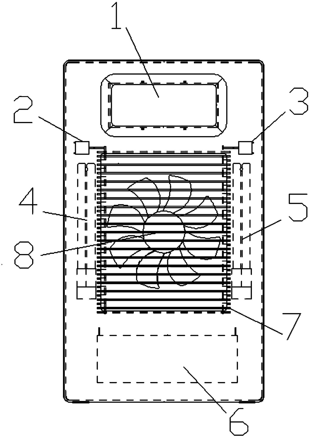
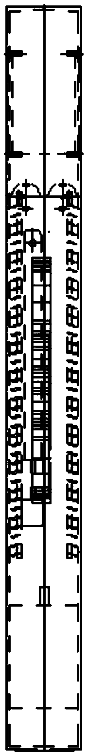
[0029] Example 1: See Figure 1-13 , an intelligent ultraviolet sterilizer, comprising a main control board 1, a left louver push-pull motor 2, a right louver push-pull motor 3, a left ultraviolet disinfection lamp tube 4, a right ultraviolet disinfection lamp tube 5, a louver blade 7 and an air supply motor 8, the The main control board 1 is embedded and installed above the main body. The main control board 1 includes an LED digital tube display and a button panel for displaying time and temperature. A blower motor 8 is provided, the left side ultraviolet disinfection lamp tube 4 and the right side ultraviolet disinfection lamp tube 5 are respectively provided on both sides of the shutter 7, and the left shutter push-pull motor 2 and the right shutter push-pull motor 3 are respectively provided on both sides of the top of the shutter 7. All shutters 7 can be switched from horizontal to vertical at any angle synchronously, the two motors operate synchronously, and a lead-acid ...

Embodiment 2

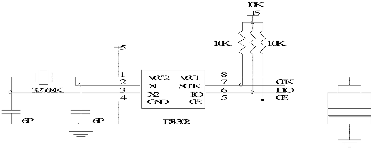
[0030] Embodiment 2. On the basis of Embodiment 1, the main control board 1 of this design includes a clock circuit, a four-digit digital tube, a four-digit digital tube drive circuit panel, a touch button circuit, a main control single-chip microcomputer, a battery power supply circuit, and a microwave radar circuit, louver motor control circuit, blower motor control circuit, lead-acid battery charging circuit and ultraviolet lamp drive circuit; the above 11 circuits correspond to Figure 3-13 The main control microcontroller is respectively connected to the clock circuit, four-digit digital tube, four-digit digital tube drive circuit panel, touch button circuit, battery power supply circuit, microwave radar circuit, louver motor control circuit, blower motor control circuit, lead-acid battery charging circuit and UV lamp drive circuit. The main control microcontroller is also connected with a temperature detection circuit. The model of the microwave radar circuit is EG4002C...


PUM


Abstract

The invention discloses an intelligent ultraviolet sterilizer. The intelligent ultraviolet sterilizer comprises a main control panel, a left louver push-pull motor, a right louver push-pull motor, a left ultraviolet sterilization lamp tube, a right ultraviolet sterilization lamp tube, louver blades and an air supply motor, wherein the main control panel is mounted above a body in an embedded manner, a louver is arranged below the main control panel, the air supply motor is arranged in the louver, the left ultraviolet sterilization lamp tube and the right ultraviolet sterilization lamp tube arearranged on two sides of the louver respectively, and the left louver push-pull motor and the right louver push-pull motor are arranged on two sides of the top of the louver respectively. Sterilization can be performed when people or animals are on the scene, when people or animals leave the scene, the louver blades are adjusted to be horizontal through rotation of the motors, the air supply motor stops rotating, the ultraviolet lamp tubes directly irradiate the periphery, and the ultraviolet sterilization range is enlarged.

Description

technical field [0001] The invention relates to a sterilizer, in particular to an intelligent ultraviolet sterilizer. Background technique [0002] Public studies have shown that ultraviolet rays kill microorganisms mainly through radiation damage to microorganisms (bacteria, viruses, spores and other pathogens) and the function of destroying nucleic acids, thereby achieving the purpose of disinfection. The effect of ultraviolet rays on nucleic acids can lead to bond and chain breaks, inter-strand crosslinks, and formation of photochemical products, etc., thereby changing the biological activity of DNA and making microorganisms unable to replicate themselves. This ultraviolet damage is also fatal damage. [0003] At present, the vast majority of ultraviolet sterilizers on the market are directly irradiated by ultraviolet lamps with no one present. Since the above methods require no one or animals on the site, the use of the product is limited, and it cannot meet the requirem...

Claims


Application Information

Patent Timeline
Patent Type & Authority Applications(China)
IPC IPC(8): A61L2/10A61L2/24A61L2/26A61L9/20
CPCA61L2/10A61L2/24A61L2/26A61L9/20A61L2209/111A61L2202/14
Inventor 苏继珍
Owner 东莞明佳美电子有限公司
Why Eureka
Try Eureka