Billet centering device

A technology of centering device and billet, applied in the field of billet centering device, can solve the problems of long production line, untimely steel mill, damage to the end of the push rod, etc., and achieve the effect of reducing length, reducing temperature drop, and buffering collision.

Active Publication Date: 2019-03-15
武汉钢铁有限公司
View PDF9 Cites 2 Cited by
  • Summary
  • Abstract
  • Description
  • Claims
  • Application Information

AI Technical Summary

Problems solved by technology

[0004] The structure of the centering device is to arrange telescopic rods on both sides of the billet respectively, and to achieve the purpose of centering the billet through the push of the rods. This method has the following problems: 1) The push rod can only work when the billet reaches the predetermined position. Therefore, the existence of the centering device will make the length of the production line longer, which is especially untimely for newly designed steel mills and does not conform to the current trend of short-process steel rolling; Strong friction will damage the end of the push rod, and there is no buffer during the whole alignment process, which is also a great test for the service life of the equipment

Method used


Image

  • Billet centering device
  • Billet centering device
  • Billet centering device

Examples


Embodiment Construction

[0020] The present invention will be further described below in conjunction with the accompanying drawings and embodiments.

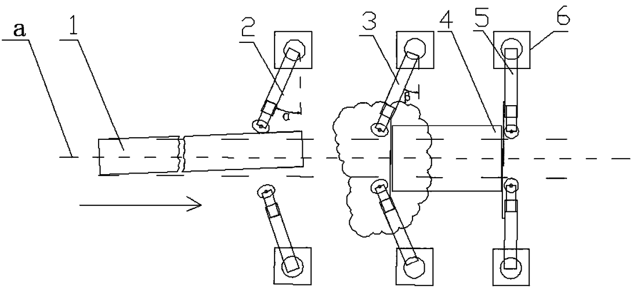
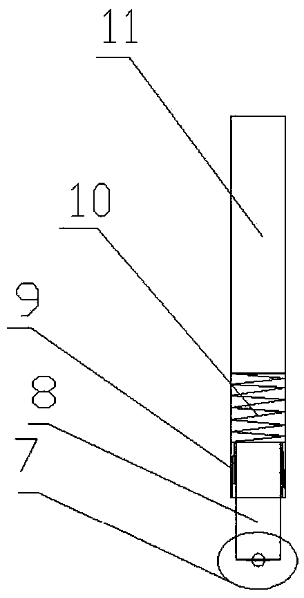
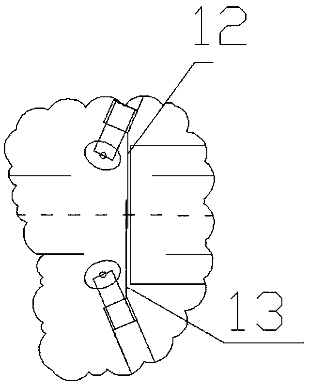
[0021] Such as figure 1 As shown, a billet centering device includes a pair of front push rods 2, a pair of middle push rods 3 and a pair of rear push rods 5, all of which are symmetrical about the center line a of the roller table. The front push rods 2 are located upstream of the middle push rods 3 , the middle push rod 3 and the rear push rod 5 are respectively located at the inlet side and the outlet side of the descaling box 4, and the ends of the front push rod 2, the middle push rod 3 and the rear push rod 5 are top wheels 7 that can be stretched along the rod direction And the restoring force of the top wheel 7 in the rod direction is provided by the main spring 10, the top wheel 7 of the front push rod 2 is biased upstream and the angle between the front push rod 2 and the vertical line a of the center line of the roller table is α, the middle ...


PUM


Abstract

The invention relates to a billet centering device, comprising a pair of front push rods, a pair of middle push rods and a pair of rear push rods all symmetric about the center line of a roller table,wherein the front push rods are located upstream of the middle push rods, the middle push rods and the rear push rods are respectively located at the inlet side and the outlet side of a descaling box, the ends of the front push rods, the middle push rods and the rear push rods are all top wheels that can be telescopically extended along the rod direction, and the restoring force of the top wheelsin the rod direction is provided by a main spring. The top wheels of the front push rods are biased upstream and the angle between the front push rods and the vertical line of the center line of theroller table is alpha, the top wheels of the middle push rods are biased upstream and the angle between the middle push rods and the vertical line of the center line of the roller table is beta, alphais greater than beta, the rear push rods are perpendicular to the center line of the roller table, and the width of the billet is W. When not in contact with the billet, the distances between the ends of the rear push rods, the ends of the middle push rods and the ends of the front push rods to the center line of the roller table increase sequentially and the distance of the ends of the rear pushrods from the center line of the roller table is W / 2. The device centers the deviation of the large offset billet, reduces the length of the production line, can buffer the collision of the billet, and is easy to maintain.

Description

technical field [0001] The invention belongs to the field of hot rolling transmission, and in particular relates to a billet centering device. Background technique [0002] After the hot continuous rolling steel billet leaves the heating furnace, it is transported by the roller table, enters the descaling box to remove the scale, and then enters the hot continuous rolling mill for rolling. During this process, billets may be misaligned. The most serious consequences of deviation will cause the hot rolling mill to pile up steel and damage the equipment. Although the side guide plates of the rolling mill have the function of guiding and centering, they have no effect on serious deviation. Big, even the side guides can be damaged under a huge impact. [0003] The billet deviation is caused by many factors, such as the levelness of the transport roller, the camber and wedge shape of the billet will lead to the misalignment of the billet. At present, the method of adding a cente...

Claims


Application Information

Patent Timeline
Patent Type & Authority Applications(China)
IPC IPC(8): B21B39/16
CPCB21B39/16
Inventor 邱碧涛陈燕才胡超熊雯张堂正张雪荣万菲张俊董元广王坤
Owner 武汉钢铁有限公司
Why Eureka
Try Eureka