Turning mechanism

A frame and organic technology, which is applied in the field of solid glue U-turn mechanism, can solve the problems of difficult solid glue, the inability to realize the uniform orientation of solid glue, and the high cost of manual feeding, so as to achieve the effect of consistent orientation

Pending Publication Date: 2019-03-15
WENZHOU HAIPAI MACHINERY TECH
View PDF1 Cites 0 Cited by
  • Summary
  • Abstract
  • Description
  • Claims
  • Application Information

AI Technical Summary

Problems solved by technology

[0002] The traditional packaging machine uses manual feeding, and the staff make the materials place in the same direction when feeding, but the cost of manual feeding is relatively high. In order to realize automatic feeding, the applicant applied to the Chinese Patent Office for the invention titled "Rotary Paper Card Seal" The invention patent of "feeding mechanism of plastic packaging machine", the authorized announcement number is CN206691446U, the feeding mechanism makes the direction of the material uniform through the U-turn device, and specifically discloses the following content: The U-turn device includes a connected feed end and a discharge end , the feed end is correspondingly arranged at the lower end of the conveyor belt; the middle part of the feed end is provided with a balance bar, and the balance bar is used to make the workpiece fall by touching the balance bar when the workpiece falls. The head falls downwards, and the inner wall of the U-turn device is also provided with two guide slopes, and a guide channel for a single workpiece that is gradually narrowed from top to bottom is formed between the two guide slopes. The discharge end is connected
This patent utilizes the difference in weight between the front and back of the material, and through the balance bar, the heavy end falls into the guide channel downward, so that the direction of the material entering the guide channel is uniform, but the front and rear weights of the solid glue are not much different, so it is difficult to ensure where the solid glue is. The end of the glue enters the guide channel downwards, so the direction of the solid glue entering the guide channel cannot be unified. Therefore, for this kind of material with uniform front and rear weights, it can only be fed manually.

Method used


Image

  • Turning mechanism
  • Turning mechanism
  • Turning mechanism

Examples


Embodiment Construction

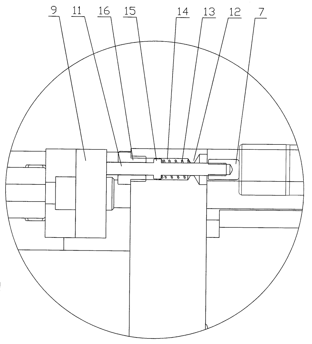
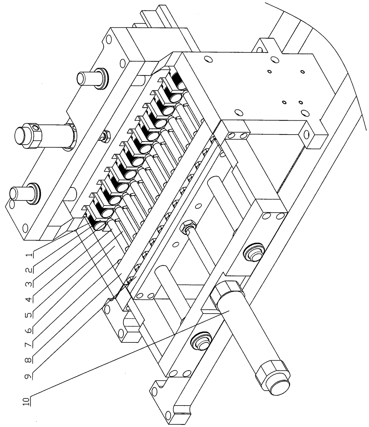
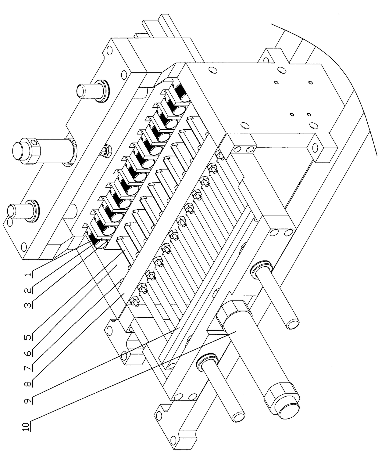
[0020] The details and working principles of the implementation modes and examples of the present invention will be described below with reference to the accompanying drawings. In this embodiment, the material conveying direction is the front, the front-back direction is the length direction, and the left-right direction is the width direction. One end of the material 1 is a plane, which is named as a plane end, and the other end has a groove, which is named as a groove end; this kind of U-turn The mechanism includes a frame, the frame is provided with a feed channel 3 and a guide channel 6, the length of the upper end of the guide channel matches the length of the material, and the lower end of the guide channel has a discharge port 17, The guide channel 6 is wide at the top and narrow at the bottom, and its vertical section is roughly Y-shaped; a stopper part that cooperates with the material 1 is provided in front of the feed channel 3, and the stopper part includes a push r...


PUM


Abstract

The invention discloses a turning mechanism, comprising a rack, and a feeding channel and a guiding channel are arranged on the rack. The turning mechanism is characterized in that the length of the upper end of the guiding channel is matched with the length of a material, a stopping part matched with the material is arranged in front of the feeding channel, the stopping part comprises an ejectorrod which moves forward and backward, and the rear end of the ejector rod is matched with the material. The turning mechanism ensures that the materials entering the guiding channel have the flat endsat the front and grooved ends at the back, and the materials are oriented in the same direction.

Description

technical field [0001] The invention relates to a U-turn mechanism, in particular to a U-turn mechanism for solid glue. Background technique [0002] The traditional packaging machine uses manual feeding, and the staff make the materials place in the same direction when feeding, but the cost of manual feeding is relatively high. In order to realize automatic feeding, the applicant applied to the Chinese Patent Office for the invention titled "Rotary Paper Card Seal" The invention patent of "feeding mechanism of plastic packaging machine", the authorized announcement number is CN206691446U, the feeding mechanism makes the direction of the material uniform through the U-turn device, and specifically discloses the following content: The U-turn device includes a connected feed end and a discharge end , the feed end is correspondingly arranged at the lower end of the conveyor belt; the middle part of the feed end is provided with a balance bar, and the balance bar is used to make...

Claims


Application Information

Patent Timeline
IPC IPC(8): B65B35/56
CPCB65B35/56Y02W30/40
Inventor 叶克勤林宣楷叶纪练
Owner WENZHOU HAIPAI MACHINERY TECH
Why Eureka
Try Eureka