Column-hanging type multifunctional heat conducting fort

A multi-functional, column-mounted technology, used in thermal storage heaters, fluid heaters, lighting and heating equipment, etc., can solve the problem of failure to meet national environmental protection requirements, excessive nitrogen oxide emissions, and large boiler footprint. To solve the problem of excessive nitrogen oxide emissions, reduce the generation of nitrogen oxides, and reduce the effect of heat dissipation

Pending Publication Date: 2019-03-15
贺全顺
View PDF0 Cites 2 Cited by
  • Summary
  • Abstract
  • Description
  • Claims
  • Application Information

AI Technical Summary

Problems solved by technology

[0002] At present, enterprises or individuals that use boilers use heat-conducting oil boilers. This kind of boiler occupies a large area, wastes energy, and discharges nitrogen oxides exceeding the standard. It does not meet the national environmental protection requirements and causes environmen

Method used


Image

  • Column-hanging type multifunctional heat conducting fort
  • Column-hanging type multifunctional heat conducting fort
  • Column-hanging type multifunctional heat conducting fort

Examples


Embodiment 1

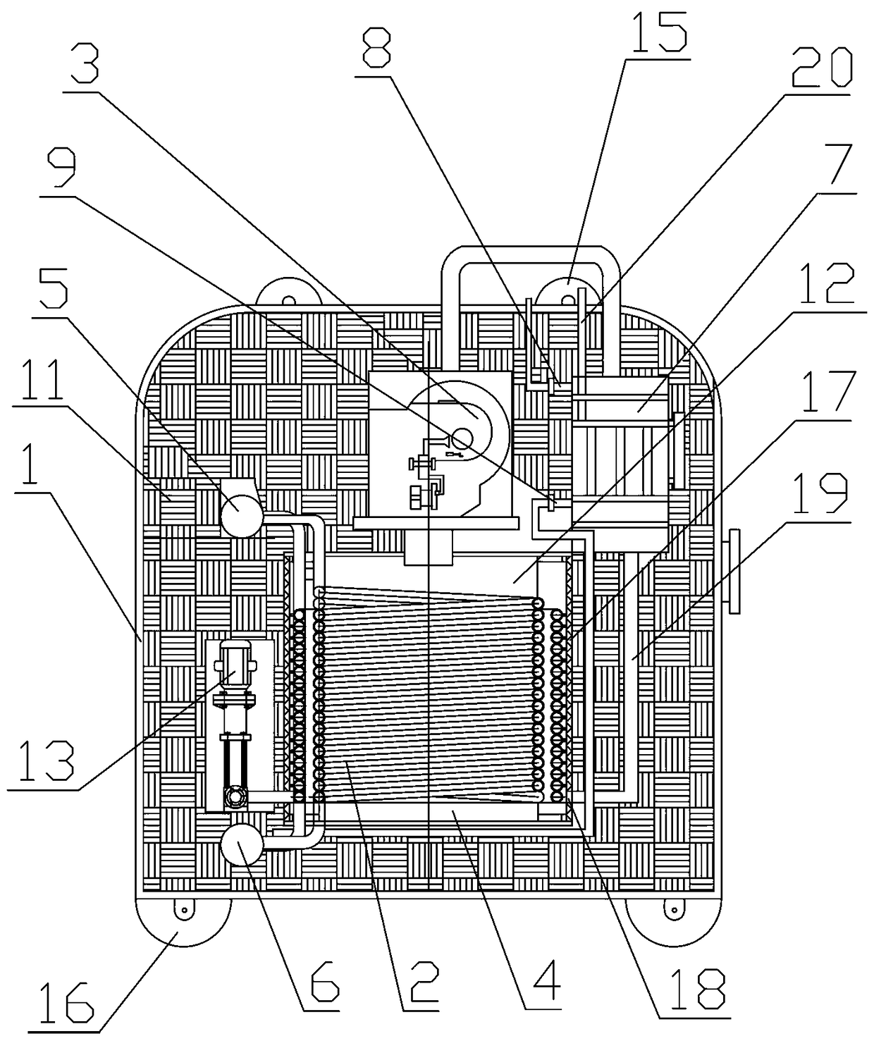
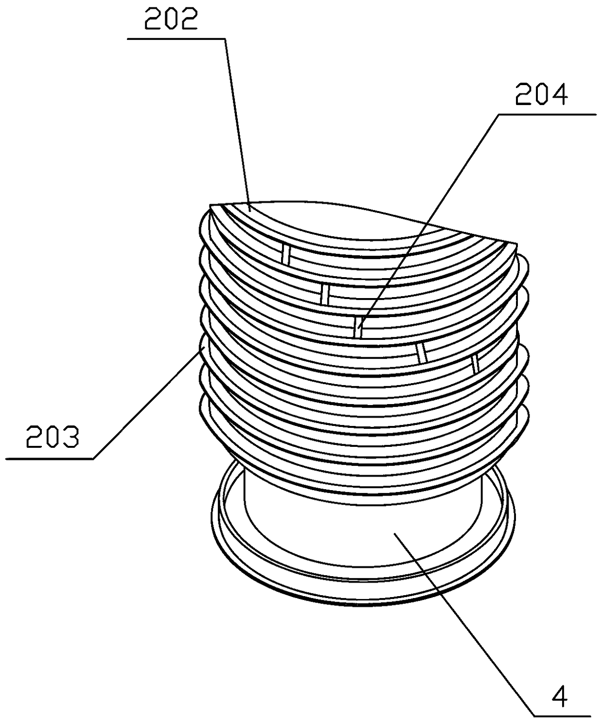
[0031] Such as Figure 1 to Figure 6 As shown, the column-mounted multifunctional heat conduction castle includes a heat conduction castle shell 1 and a burner 3 arranged in the upper middle of the inner cavity of the heat conduction castle shell 1, and a double-layer heat pipe is vertically arranged in the middle of the inner cavity of the heat conduction castle shell 1, The double-layer heat pipe is composed of an inner heat pipe 201 and an outer heat pipe 202. Both the inner heat pipe 201 and the outer heat pipe 202 are in the shape of a spiral coil, and the middle part of the inner heat pipe 201 forms a first gas channel. 21. The inner layer heat pipe 201 is fixed to the middle of the outer layer heat pipe 202 with a space between them to form the second gas passage 22, and the double layer heat pipe forms the heat conduction fortress 2. In this embodiment, the inner layer heat pipe 201 The top of the top exceeds the top of the outer heat pipe 202, so that the height of th...

Embodiment 2

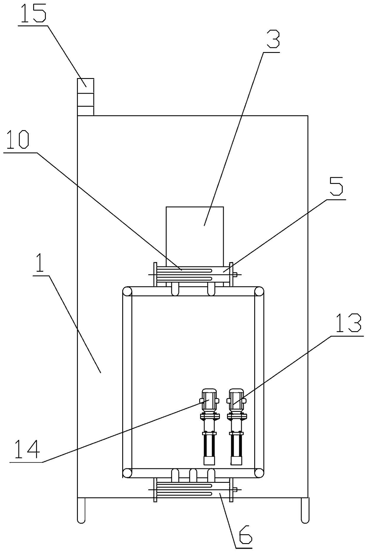
[0046] This embodiment is basically the same as Embodiment 1, and the similarities will not be repeated. The difference is: the column-hanging multifunctional heat conduction castle, the upper header 5 and the lower header 6 are both hollow structures, and the upper header A heating element 10 is provided in the middle of the inner cavity of the tank 5 and the lower header 6. Specifically, the heating element 10 in this embodiment is an electric heating tube. When the burner 3 is damaged, the oil or water is heated through the heating element 10. Then through the outlet provided on the upper header 5, heat is provided for the user. The setting of the heating element 10 enables the present invention to achieve the purpose of interoperability of oil, gas and electricity, and realize multi-functional operations.


PUM


Abstract

The invention relates to a column-hanging type multifunctional heat conducting fort comprising a heat conducting fort shell and a burner arranged on the upper middle portion of an inner cavity of theheat conducting fort shell. A double-layer heat conducting pipe is vertically arranged at the middle portion of the inner cavity of the heat conducting fort shell, the double-layer heat conducting pipe forms a heat conducting fort body, the exterior of the heat conducting fort body is surrounded by a heat conducting pipe shell, an upper end outlet of the heat conducting fort body is connected to an upper header, and a lower end inlet of the heat conducting fort body is connected to a lower header; and the upper side of the inner cavity of the heat conducting fort shell is provided with a wasteheat purification device, the waste heat purification device communicates with the burner, and the waste heat purification device further communicates with the lower header through a high temperatureoil pump and a high temperature water pump. The column-hanging type multifunctional heat conducting fort is small in floor space, high in heating speed and free of pollution, does not require workersto install on site, saves cost and improves efficiency.

Description

technical field [0001] The invention relates to the field of environmental protection heat conduction equipment, in particular to a column-hung multifunctional heat conduction fort. Background technique [0002] At present, enterprises or individuals that use boilers use heat-conducting oil boilers. This kind of boiler occupies a large area, wastes energy, and discharges nitrogen oxides exceeding the standard. It does not meet the national environmental protection requirements and causes environmental pollution. The boiler needs to be assembled and assembled on site. After installation, professional construction personnel are needed, which increases the installation cost, and the current boiler can only be used for natural gas to generate heat, with single function and poor practicability. Contents of the invention [0003] The object of the present invention is to provide a column-hung multifunctional heat conduction castle with small footprint, low cost, fast heating spe...

Claims


Application Information

Patent Timeline
IPC IPC(8): F22B1/22F24H7/00F23C9/06
CPCF22B1/22F23C9/06F24H7/005
Inventor 贺珂宇孙启明贺凯杨子涵贺全顺
Owner 贺全顺
Why Eureka
Try Eureka