
Vehicle-mounted missile launching single-side flow director and launching vehicle with same

A missile launch and deflector technology, applied in the direction of the launch device, etc., can solve the problems of reducing the impact force of the gas flow on the deflector, damage, weak shear resistance of the hydraulic outriggers, etc., so as to reduce the risk of damage and reduce the Shear force, the effect of improving reliability

Inactive Publication Date: 2019-03-15
THE GENERAL DESIGNING INST OF HUBEI SPACE TECH ACAD
View PDF7 Cites 7 Cited by
  • Summary
  • Abstract
  • Description
  • Claims
  • Application Information

AI Technical Summary

Problems solved by technology

[0004] Launch vehicles using single-sided diversion devices generally fix the diversion devices on the launch platform, and at the same time, the launch platform is hinged to the rear beam rotary shaft on the chassis of the launch vehicle. Before launch, the hydraulic legs are adjusted to support the launch vehicle. Rotate to the upright state; when launching, the missile gas flow is ejected, and the flow guide device guides the downwardly injected gas flow to the rear, and the flow guide device is subjected to the impact force of the gas flow, and the impact force has a horizontal direction to the front of the vehicle. The component force needs to be balanced by the friction between the hydraulic outrigger and the ground. Due to the weak shear resistance of the hydraulic outrigger, the risk of damage under the impact of the gas flow is relatively high, which reduces the safety of the entire launch system. reliability, therefore, it is necessary to reduce the impact force of the gas flow on the deflector

Method used


Image

  • Vehicle-mounted missile launching single-side flow director and launching vehicle with same
  • Vehicle-mounted missile launching single-side flow director and launching vehicle with same
  • Vehicle-mounted missile launching single-side flow director and launching vehicle with same

Examples


Embodiment 1

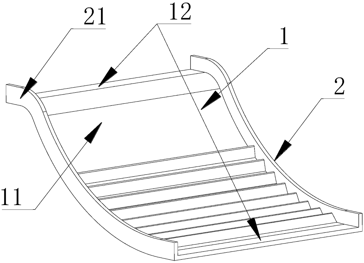
[0033] see figure 1 As shown, the embodiment of the present invention provides a vehicle-mounted missile launching single-sided deflector, including:

[0034] The flow guide part 1, the flow guide part 1 includes a downwardly concave arc-shaped main profile 11, and connecting surfaces 12 respectively connected to both sides of the head and tail of the main profile 11, the main profile 11 A plurality of convex lines 13 are arranged at intervals on the upper surface of the upper surface, and the plurality of convex lines 13 run through the entire main surface 11 in a transverse direction;

[0035] A bracket 2 for supporting the deflector 1, and the bracket 2 is detachably connected with the launching platform.

[0036] The vehicle-mounted missile launch single-sided deflector of the present invention adopts a plurality of convex lines 13 on the downwardly concave arc-shaped main profile 11. When the vehicle-mounted missile is launched, a part of the missile gas flow injected do...

Embodiment 2

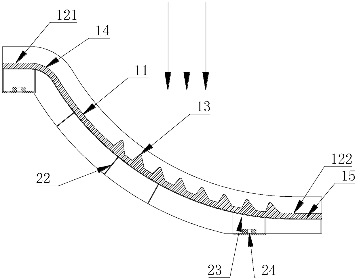
[0043] see figure 1 and figure 2 As shown, the embodiment of the present invention provides a vehicle-mounted missile launching single-sided deflector, including:

[0044] The flow guide part 1, the flow guide part 1 includes a downwardly concave arc-shaped main profile 11, and connecting surfaces 12 respectively connected to both sides of the head and tail of the main profile 11, the main profile 11 A plurality of convex lines 13 are arranged at intervals on the upper surface of the upper surface, and the plurality of convex lines 13 run through the entire main surface 11 in a transverse direction;

[0045] A bracket 2 for supporting the deflector 1, and the bracket 2 is detachably connected with the launching platform.

[0046] The vehicle-mounted missile launch single-sided deflector of the present invention adopts a plurality of convex lines 13 on the downwardly concave arc-shaped main profile 11, and the direction of the arrow in the figure is the gas flow injection di...

Embodiment 3

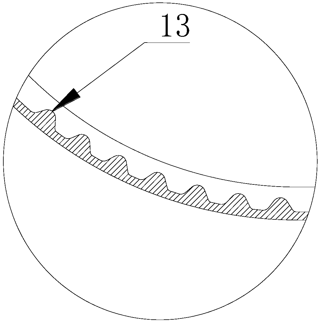
[0049] see figure 1 and image 3 As shown, the embodiment of the present invention provides a vehicle-mounted missile launching single-sided deflector, including:

[0050] The flow guide part 1, the flow guide part 1 includes a downwardly concave arc-shaped main profile 11, and connecting surfaces 12 respectively connected to both sides of the head and tail of the main profile 11, the main profile 11 A plurality of convex lines 13 are arranged at intervals on the upper surface of the upper surface, and the plurality of convex lines 13 run through the entire main surface 11 in a transverse direction;

[0051] A bracket 2 for supporting the deflector 1, and the bracket 2 is detachably connected with the launching platform.

[0052] The vehicle-mounted missile launch single-sided deflector of the present invention adopts a plurality of convex lines 13 on the downwardly concave arc-shaped main profile 11. When the vehicle-mounted missile is launched, a part of the missile gas fl...


PUM


Abstract

The invention discloses a vehicle-mounted missile launching single-side flow director and a launching vehicle with the same, and relates to the technical field of missile launching equipment. The vehicle-mounted missile launching single-side flow director comprises a flow guide part and a support, wherein the flow guide part comprises an arc-shaped main molded surface which is recessed downwardsand a connecting surface which is correspondingly connected with the head side and the tail side of the main molded surface, a plurality of convex strips are arranged on the upper surface of the mainmolded surface at intervals, the plurality of convex strips transversely penetrate through the whole main molded surface, the support is used for supporting the flow guide part, and the support is detachably connected with a launching station. According to the vehicle-mounted missile launching single-side flow director and the launching vehicle with the same, part of the acting force in the direction of the vehicle head can be counteracted, so that the shearing force generated by friction between hydraulic supporting legs and the ground is reduced, the risk that the hydraulic supporting legs are damaged under the action of the impact force of the fuel gas flow is reduced, and the reliability of a whole launching system is improved.

Description

technical field [0001] The invention relates to the technical field of missile launch equipment, in particular to a vehicle-mounted missile launch single-sided deflector and a launch vehicle with the deflector. Background technique [0002] The launch of medium and short-range ground-to-ground tactical ballistic missiles generally adopts the vehicle-mounted thermal launch method, and the vehicle-mounted thermal launch vehicle is generally equipped with a flow guide device, which is used to guide the high-temperature, high-speed gas flow ejected when the missile is launched. In order to prevent the gas flow from eroding and damaging the launch pad facilities and equipment, and at the same time prevent the gas and combustion residue from rebounding after impacting the ground and affecting the missile body. [0003] The vehicle-mounted heat emission gas guide device can be divided into two types: single-side guide device and double-side guide device. The single-side guide devic...

Claims


Application Information

Patent Timeline
Patent Type & Authority Applications(China)
IPC IPC(8): F41F1/00
CPCF41F1/00
Inventor 吴穹
Owner THE GENERAL DESIGNING INST OF HUBEI SPACE TECH ACAD
Learn More