
Switch and electric tool with same

A switch and circuit board technology, applied in the direction of electric switches, circuits, electrical components, etc., can solve the problem of low output power of switches

Pending Publication Date: 2019-03-15
SHANGHAI BAICHENG ELECTRONICS
View PDF0 Cites 1 Cited by
  • Summary
  • Abstract
  • Description
  • Claims
  • Application Information

AI Technical Summary

Problems solved by technology

[0003] The main purpose of the present invention is to provide a switch and an electric tool with it, so as to solve the problem of low output power of switches in the prior art

Method used


Image

  • Switch and electric tool with same
  • Switch and electric tool with same
  • Switch and electric tool with same

Examples


Embodiment Construction

[0050] It should be noted that, in the case of no conflict, the embodiments in the present application and the features in the embodiments can be combined with each other. The present invention will be described in detail below with reference to the accompanying drawings and examples.

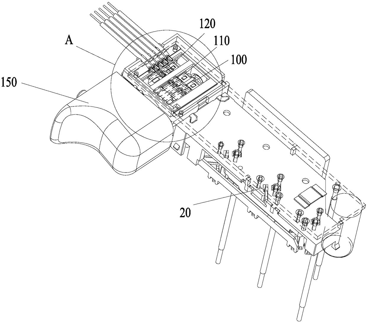
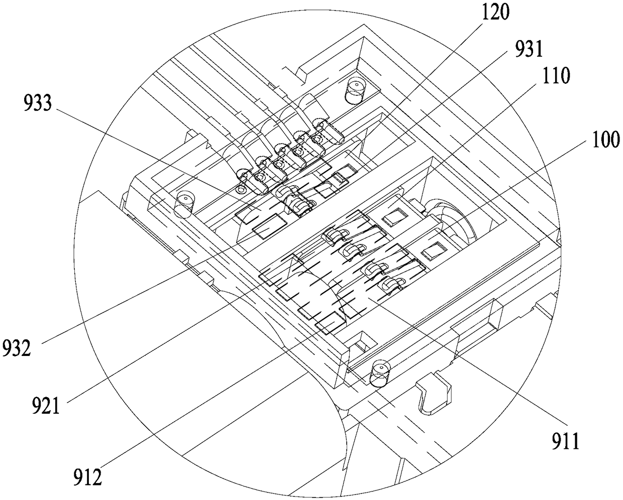
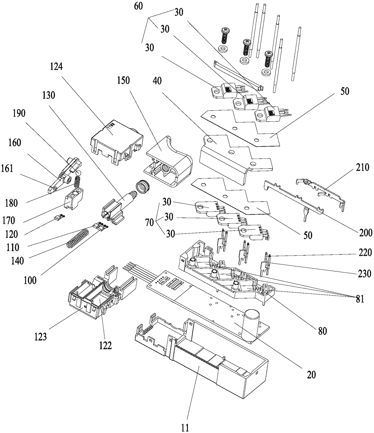
[0051] Such as Figure 1 to Figure 7 As shown, the switch of this embodiment includes: a housing 10 , a circuit board 20 and a TO-220 packaged MOS transistor 30 . Wherein, the circuit board 20 is arranged in the housing 10 . The MOS tubes 30 packaged in TO-220 are connected to the circuit board 20. The MOS tubes 30 are divided into two groups, and each group contains three MOS tubes 30. The two groups of MOS tubes 30 are arranged symmetrically along the plane parallel to the circuit board 20, and the two groups of MOS tubes The tubes 30 are located on the same side of the circuit board 20 , and the MOS tubes 30 are arranged obliquely relative to the extending direction of the circuit board 20...


PUM


Abstract

The invention provides a switch and an electric tool with the same. The switch comprises a shell, a circuit board arranged in the shell, and two groups of MOS transistors packaged by TO-220 and connected with the circuit board; each group of the MOS transistors comprises three MOS transistors; the two groups of the MOS transistors are symmetrically arranged in a plane parallel to the circuit board; the two groups of the MOS transistors are located on the same side of the circuit board; each MOS transistor is obliquely arranged relative to an extending direction of the circuit board; and inclination directions of all the MOS transistors are the same. By applying the technical scheme, the problem of low output power of the switch in the prior art can be effectively solved.

Description

technical field [0001] The invention relates to the field of tools, in particular to a switch and an electric tool with the same. Background technique [0002] At present, there are two commonly used brushless switches for electric tools on the market, one is a separate switch and the other is an integrated switch. For the separate switch, the switch part is separated from the control part of the motor. When the switch is installed on the electric tool, the installation is relatively troublesome and the installation efficiency is low. Although the integrated switch can solve the low installation efficiency, due to the limited installation space, the volume of the integrated switch cannot be too large, which leads to the switch only using a small-sized SMD-packaged MOS tube, resulting in poor heat dissipation performance. , the output power is low, and the cost is relatively high. Contents of the invention [0003] The main purpose of the present invention is to provide a...

Claims


Application Information

Patent Timeline
Patent Type & Authority Applications(China)
IPC IPC(8): H01H9/54H01H9/52
CPCH01H9/52H01H9/547
Inventor 谭和平
Owner SHANGHAI BAICHENG ELECTRONICS
Learn More