Optical resonator, method of manufacturing the optical resonator and applications thereof

An optical resonator, resonator technology, applied in the structure/shape of optical resonator, optics, lasers, etc., to achieve the effect of promoting compatibility

Inactive Publication Date: 2019-03-15
CSEM CENT SUISSE DELECTRONIQUE & DE MICROTECHNIQUE SA RECH & DEV
View PDF10 Cites 3 Cited by
  • Summary
  • Abstract
  • Description
  • Claims
  • Application Information

AI Technical Summary

Problems solved by technology

Therefore, dispersion engineering is limited to the choice of fiber materials

Method used


Image

  • Optical resonator, method of manufacturing the optical resonator and applications thereof
  • Optical resonator, method of manufacturing the optical resonator and applications thereof
  • Optical resonator, method of manufacturing the optical resonator and applications thereof

Examples


Embodiment Construction

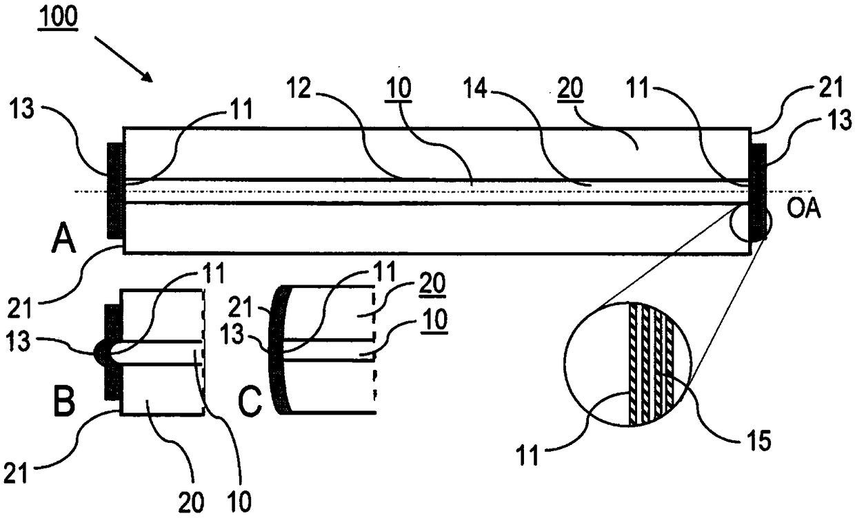
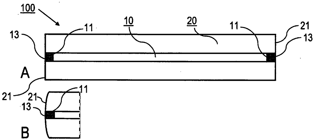
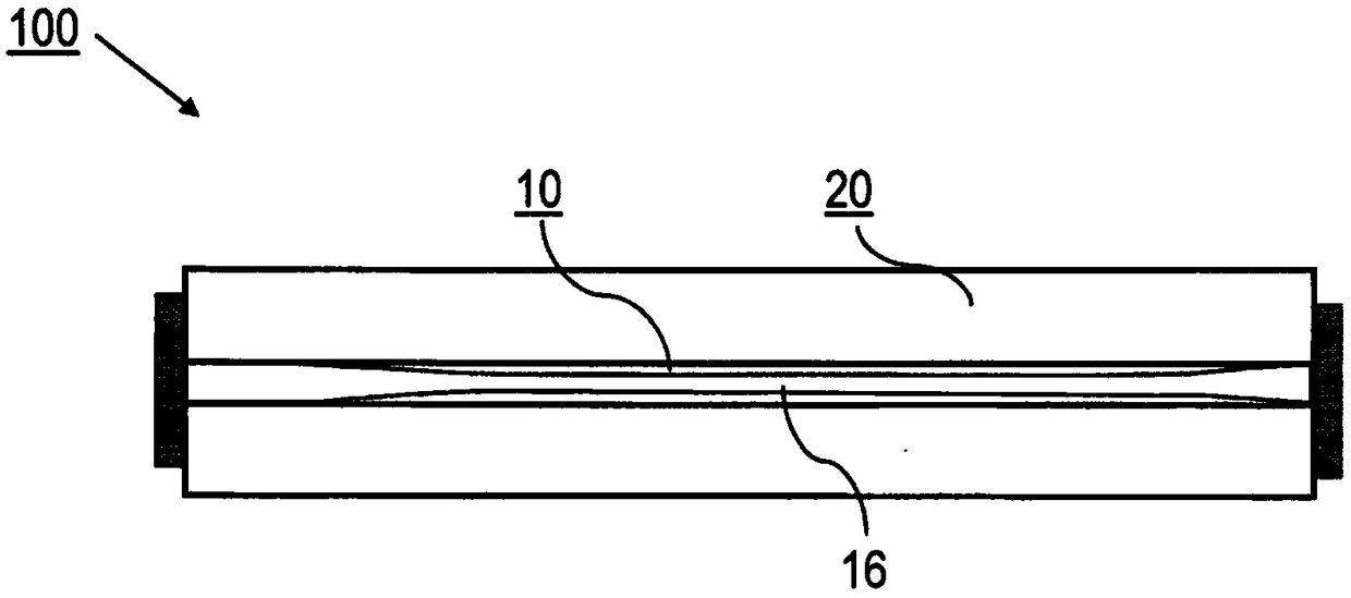
[0055]Embodiments of the invention are described below with reference to the example of an optical resonator comprising an optical fiber as an optical waveguide. It is emphasized that the invention is not limited to the use of optical fibers, but may be used for other types of optical waveguides, such as solid rods of (potentially doped) glass, crystals or semiconductor materials. Furthermore, the use of single-mode fibers as optical waveguides is specifically mentioned. Implementation of the invention is not limited to this example, but is possible for other types of optical fibers as described above.

[0056] The figures show an enlarged cross-sectional view of an optical resonator, wherein details of the resonator are schematically shown for illustrative purposes. In practice, especially the thickness of the resonator mirror and the diameter of the optical waveguide are much smaller compared to the dimensions of the ferrule.

[0057] Figure 1-5 An embodiment of an optic...


PUM


Abstract

An optical resonator (100) comprises an optical waveguide device (10) having an optical axis (OA) and extending with a longitudinal length between two waveguide end facets (11), resonator mirrors (13)being arranged for enclosing a resonator section (14) of the optical waveguide device (10), and a ferrule (20) having two ferrule facets (21), wherein the optical waveguide device (10) is mounted tothe ferrule (20) and the ferrule (20) extends along the full longitudinal length of optical waveguide device (10). Furthermore, an optical apparatus (200) including the optical resonator (100) and a method of manufacturing the optical resonator (100) are described.

Description

technical field [0001] The present invention relates to an optical resonator comprising an optical waveguide, such as an optical fiber, mounted to a ferrule. Furthermore, the present invention relates to an optical device including an optical resonator, a method of manufacturing the optical resonator, and applications of the optical resonator. The invention can be applied in the field of linear or nonlinear, active or passive laser optics, especially for broadband optical frequency generation, optical pulse generation, ultra-low noise microwave generation, spectroscopy, pulsed or continuous wave laser or laser frequency stabilization change. Background technique [0002] Optical resonators, especially optical microresonators, are generally regarded as a rapidly developing technology platform with a wide range of applications ranging from fundamental physics to applications such as spectroscopy, low-noise microwave generation, and optical data transmission. Different resona...

Claims


Application Information

Patent Timeline
Patent Type & Authority Applications(China)
IPC IPC(8): H01S3/06H01S3/067H01S3/08
CPCH01S3/0621H01S3/0627H01S3/06725H01S3/06741H01S3/0675H01S3/08045H01S2301/085G02B6/29359G02B6/3845G02B6/3846H01S3/06704
Inventor 托比亚斯·赫尔史蒂夫·勒科米特
Owner CSEM CENT SUISSE DELECTRONIQUE & DE MICROTECHNIQUE SA RECH & DEV
Why Eureka
Try Eureka