Power conversion device
A power conversion device and control device technology, which is applied in the direction of output power conversion device, AC power input conversion to DC power output, irreversible DC power input conversion to AC power output, etc. The detector cannot detect the maximum phase current detection value and other problems
- Summary
- Abstract
- Description
- Claims
- Application Information
AI Technical Summary
Problems solved by technology
Method used
Image

Examples
Embodiment approach 1
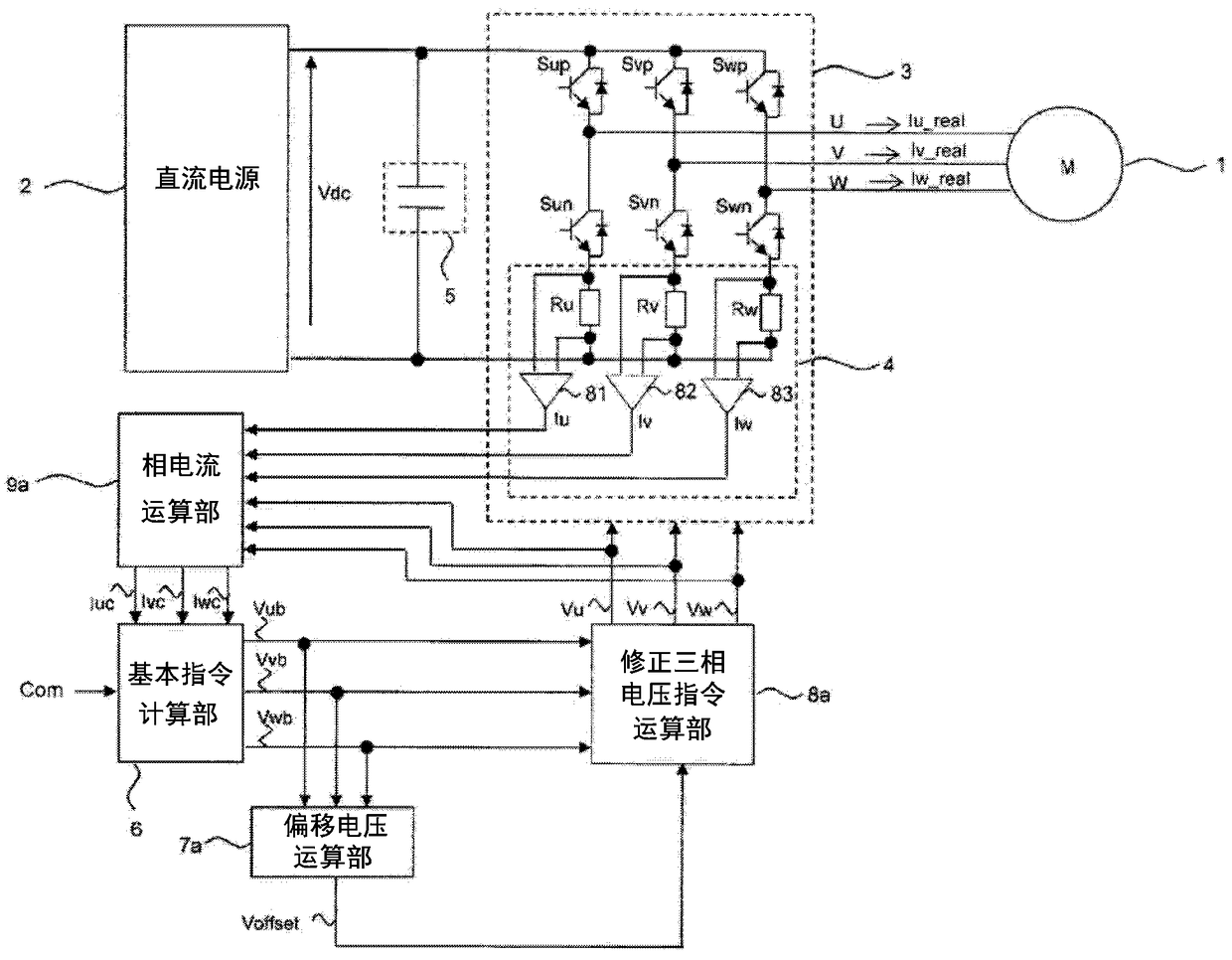
[0110] figure 1 It is an overall configuration diagram of the power conversion device according to Embodiment 1 of the present invention. exist figure 1 Among them, the power conversion device according to Embodiment 1 of the present invention includes a three-phase inverter 3, a current detector 4, a filter capacitor 5, a basic command computing unit 6, an offset voltage computing unit 7a, and a corrected three-phase voltage command computing unit. 8a and the phase current computing unit 9a. Here, the basic command calculation unit 6, the offset voltage calculation unit 7a, the corrected three-phase voltage command calculation unit 8a, and the phase current calculation unit 9a constitute a control device in the power conversion device, and the control device is a microcomputer operating based on a predetermined program. constitute.
[0111] The positive terminal and the negative terminal of the three-phase inverter 3 are connected to the positive side and the negative side...
Embodiment approach 2
[0206] Next, a power conversion device according to Embodiment 2 of the present invention will be described. The overall configuration diagram of the power conversion device according to Embodiment 2 of the present invention is the same as the above-mentioned figure 1 same. The power conversion device according to the second embodiment differs from the power conversion device according to the first embodiment in the configuration of the offset voltage calculation unit and the detection timing of the current detection value. In the following description, differences from Embodiment 1 will be mainly described.
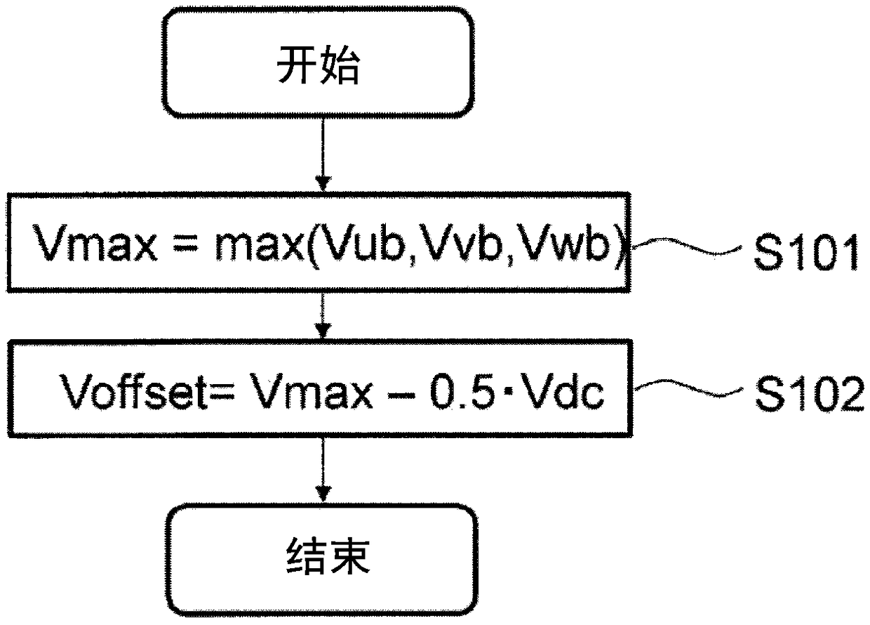
[0207] Figure 8 It is a flowchart showing the calculation procedure of the offset voltage calculation unit in the power conversion device according to Embodiment 2 of the present invention. figure 1 The shown offset voltage calculation unit 7b calculates the offset voltage Voffset based on the U-phase voltage command Vub, the V-phase voltage command Vvb, and the W-ph...
Embodiment approach 3
[0216] Next, a power conversion device according to Embodiment 3 of the present invention will be described. The overall configuration diagram of the power conversion device according to Embodiment 2 of the present invention is the same as the above-mentioned figure 1 same. The power conversion device according to Embodiment 3 is different from the power conversion device according to Embodiment 2 in the detection timing of the current detection value and the configuration of the phase current calculation unit 9b. In the following description, differences from Embodiment 2 will be mainly described. Figure 11 It refers to the PWM carrier signal, the corrected three-phase voltage command, each switching element of the three-phase inverter, the U-phase lower arm switching element, and the V-phase upper arm switching element in the power conversion device according to the third embodiment of the present invention. An explanatory diagram for explaining the carrier cycle Tc.
[02...
PUM
 Abstract
Description
Claims
Application Information
 - R&D
- Intellectual Property
- Life Sciences
- Materials
- Tech Scout
- Unparalleled Data Quality
- Higher Quality Content
- 60% Fewer Hallucinations
Browse by: Latest US Patents, China's latest patents, Technical Efficacy Thesaurus, Application Domain, Technology Topic, Popular Technical Reports.
© 2025 PatSnap. All rights reserved.Legal|Privacy policy|Modern Slavery Act Transparency Statement|Sitemap|About US| Contact US: help@patsnap.com