A wire bending device

A bending device and wire technology, applied in the field of electric equipment, can solve problems such as difficulties, damaged materials, and damaged wire insulation layers, and achieve the effects of speeding up electric power construction, reducing difficulty in electric power construction, and increasing production speed

Active Publication Date: 2020-06-26
国网山东省电力公司单县供电公司
View PDF6 Cites 0 Cited by
  • Summary
  • Abstract
  • Description
  • Claims
  • Application Information

AI Technical Summary

Problems solved by technology

However, it is very difficult for operators to operate with bare hands in order to meet the required standards for wire connection and wiring technology
It not only requires the operator to have high operating skills, but also has a certain amount of arm strength, otherwise it will not only take time and effort, but also damage the material
For example, when using copper wires with a cross-sectional area of ​​more than 6mm, some workers are tired and sweaty because they are not strong enough, and an electric energy meter has not been installed. Some people use wire cutters to bend the wires to save effort. It will damage the insulation layer of the wire and cause a safety hazard.

Method used


Image

  • A wire bending device
  • A wire bending device
  • A wire bending device

Examples


Embodiment Construction

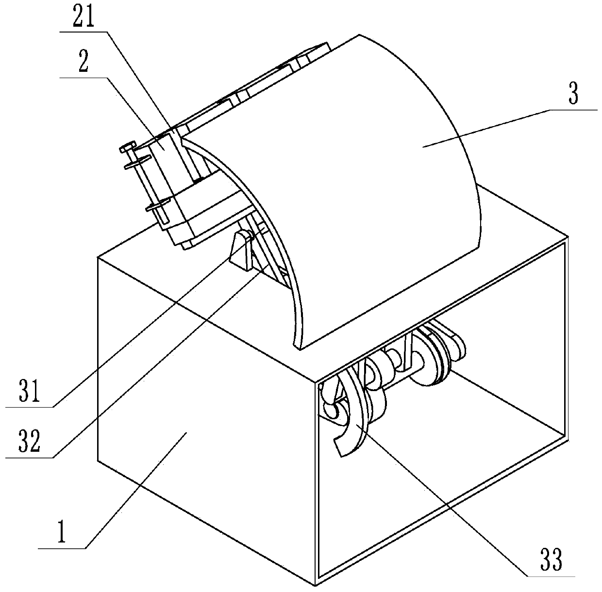
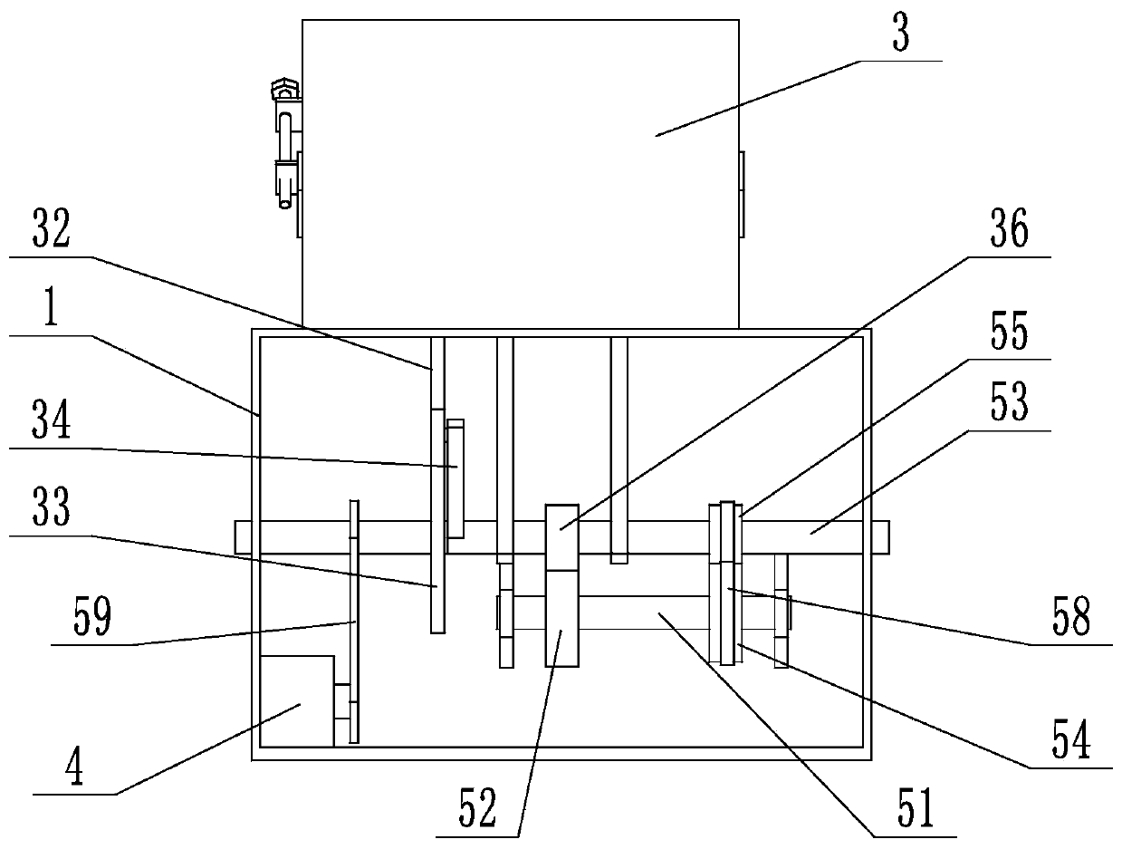
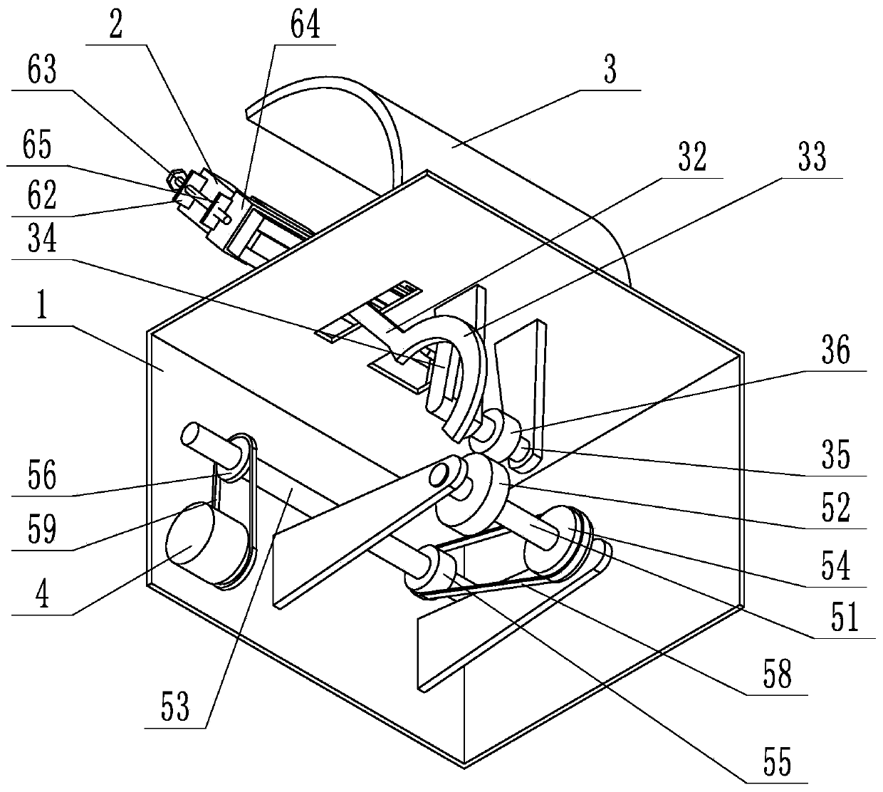
[0028] In order to clearly illustrate the technical characteristics of this program, the following specific implementation methods, combined with its attached Figures 1 to 9 , the present invention is described in detail. The following disclosure provides many different embodiments or examples for implementing different structures of the present invention. To simplify the disclosure of the present invention, components and arrangements of specific examples are described below. Furthermore, the present invention may repeat reference numerals and / or letters in different instances. This repetition is for the purpose of simplicity and clarity and does not in itself indicate a relationship between the various embodiments and / or arrangements discussed. It should be noted that components illustrated in the figures are not necessarily drawn to scale. Descriptions of well-known components and processing techniques and processes are omitted herein to avoid unnecessarily limiting the...


PUM


Abstract

The invention discloses a wire bending device. The wire bending device comprises a box body, a wire passing board and a baffle, wherein the wire passing board is rotationally arranged at the upper endof the box body, the baffle is fixedly arranged at the upper end of the box body, a wire passing hole is formed in the wire passing board, a first rotating shaft is rotationally arranged at the upperend of the box body through a bearing, the wire penetrating board is fixed to a first rotating shaft through a first connecting rod and a second connecting rod, the other end of the first connectingrod is connected with the first rotating shaft and then extends into the box body, a motor is arranged in the box body, the motor drives the first connecting rod to swing around the first rotating shaft, a circular arc-shaped guide rod is fixedly arranged at the inner end part of the box body, a semicircular guide rail is arranged on the arc-shaped guide rod, a swing rod is arranged on one side ofthe arc-shaped guide rod, the swing rod is fixedly arranged on a second rotating shaft, the second rotating shaft is rotationally arranged inside the box body through a bearing, a roller is arrangedat the free end of the swing rod, and the roller is arranged in the guide rail of the arc-shaped guide rod in a sliding mode. According to the wire bending device, the bending speed of a wire is increased, and the construction speed is accelerated.

Description

technical field [0001] The invention relates to the technical field of electric equipment, in particular to a wire bending device. Background technique [0002] Install the power distribution cabinet, the electric energy meter and other electrical equipment connection wires in the cabinet require the wires to be bent wires with a certain angle, and the insulation layer of the wires should not be damaged. However, it is very difficult for operators to operate with bare hands in order to achieve the required standard for wire connection and wiring technology. It not only requires the operator to have high operating skills, but also has a certain amount of arm strength, otherwise it will not only take time and effort, but also damage the material. For example, when using copper wires with a cross-sectional area of ​​more than 6mm, some workers are tired and sweaty because they are not strong enough, and an electric energy meter has not been installed. Some people use wire cutt...

Claims


Application Information

Patent Timeline
Patent Type & Authority Patents(China)
IPC IPC(8): B21F1/00
CPCB21F1/00
Inventor 王志勇孙东风张旺鲁克苏启征刘冬赵静王磊王晨光祝凤兰孙洁
Owner 国网山东省电力公司单县供电公司
Why Eureka
Try Eureka