Prefabricated box girder steel bar binding and positioning jig frame

A technology for tying steel bars and positioning tires, which is used in manufacturing tools, ceramic molding machines, building structures, etc., can solve the problems of time-consuming and laborious handling of semi-finished steel bars, restricting construction progress by quality and speed, and low qualification rate of steel protective layers. It is convenient for multi-position lifting and adjustment, improving convenience, and the effect of convenient adjustment

Active Publication Date: 2019-03-19
CHINA CONSTR SENVENTH ENG BUREAU INSTALLATION ENG
View PDF5 Cites 8 Cited by
  • Summary
  • Abstract
  • Description
  • Claims
  • Application Information

AI Technical Summary

Problems solved by technology

The traditional prefabricated box girder reinforcement is bound directly on the girder pedestal. Due to factors such as the dispersion of the beam pedestal, it takes time and effort to transport the semi-finished steel bars, the pass rate of the steel bar cover is low, the line shape of the steel bar skeleton is poor, and the spacing between the steel bars is uneven. , The steel skeleton is polluted by the release agent of the steel plate of the controlled beam pedestal, and the pedestal has a long turnover period.
The quality and speed of traditional prefabricated box girder reinforcement binding often restrict the construction progress of on-site prefabricated box girders; at the same time, during the construction process, when the steel bars need to be adjusted, multiple people need to lift them up, and the operation is very troublesome. Therefore, we propose a Prefabricated box girder reinforcement binding positioning tire frame

Method used


Image

  • Prefabricated box girder steel bar binding and positioning jig frame
  • Prefabricated box girder steel bar binding and positioning jig frame
  • Prefabricated box girder steel bar binding and positioning jig frame

Examples


Embodiment Construction

[0024] The following will clearly and completely describe the technical solutions in the embodiments of the present invention with reference to the accompanying drawings in the embodiments of the present invention. Obviously, the described embodiments are only some, not all, embodiments of the present invention.

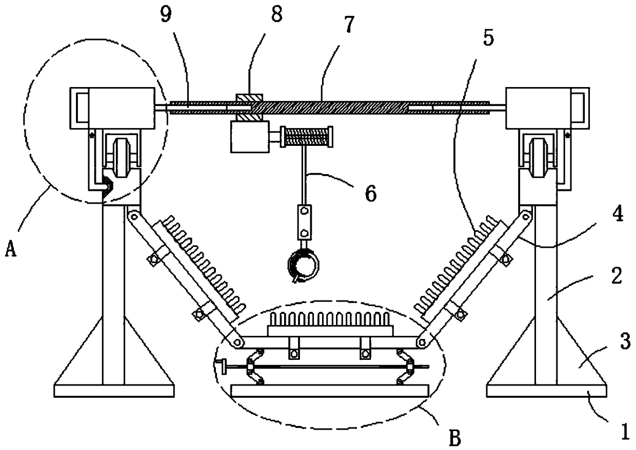
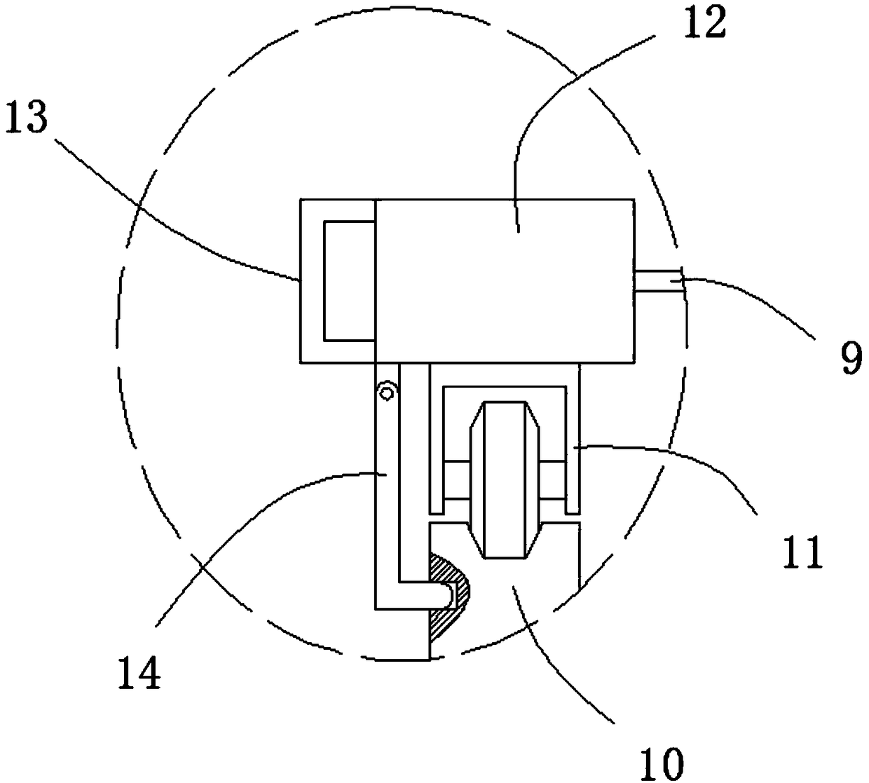
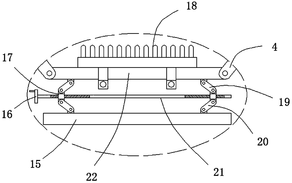
[0025] refer to Figure 1-6 , a prefabricated box girder reinforcement binding positioning tire frame, including a first bottom plate 1 and a second bottom plate 15, the first bottom plate 1 is provided with two, and the top of the first bottom plate 1 is welded with a plurality of equidistantly arranged support columns 2, The top of the support column 2 is fixed with a fixed bar 10, the top of the fixed bar 10 is provided with a rolling groove, the top of the fixed bar 10 is provided with a moving block 12, the bottom of the moving block 12 is equipped with a roller 11, and the roller 11 is rolled and installed in the rolling groove , a first bushing 7 is arranged b...


PUM


Abstract

The invention discloses a prefabricated box girder steel bar binding and positioning jig frame which comprises first bottom plates and a second bottom plate. The two first bottom plates are arranged,and multiple supporting pillars which are arranged at equal intervals are welded to the tops of the first bottom plates. Fixing bars are fixed to the tops of the supporting pillars. Rolling grooves are formed in the tops of the fixing bars, and moving blocks are arranged above the fixing bars. Wheels are arranged at the bottoms of the moving blocks, and the wheels are installed in the rolling grooves in a rolling manner. A first casing pipe is arranged between the two moving blocks, and first sliding rods are connected in the two ends of the first casing pipe in a sliding and sleeved manner. The ends, back to each other, of the two first sliding rods are fixed to the moving blocks on the two sides, a sliding block is connected to the outer portion of the first casing pipe in a sliding andsleeving manner, and a lifting device is installed at the bottom of the sliding block. By means of the prefabricated box girder steel bar binding and positioning jig frame, position adjustment can beconducted on a steel bar, the labor intensity is greatly lowered, and operation convenience is improved.

Description

technical field [0001] The invention relates to the technical field of tire frame positioning, in particular to a prefabricated box girder steel bar binding positioning tire frame. Background technique [0002] Since the binding of the steel skeleton is the most workload, the most cumbersome and the longest time-consuming in the prefabricated box girder production operation, it is an important link in the box girder prefabrication. The traditional prefabricated box girder reinforcement is bound directly on the girder pedestal. Due to factors such as the dispersion of the beam pedestal, it takes time and effort to transport the semi-finished steel bars, the pass rate of the steel bar cover is low, the line shape of the steel bar skeleton is poor, and the spacing between the steel bars is uneven. , The steel skeleton is polluted by the release agent of the steel plate of the controlled beam pedestal, and the pedestal has a long turnover period. The quality and speed of tradit...

Claims


Application Information

Patent Timeline
Patent Type & Authority Applications(China)
IPC IPC(8): B28B23/04E04G21/12
CPCB28B23/04E04G21/12
Inventor 卢来运江锁李杨李阳林海兴
Owner CHINA CONSTR SENVENTH ENG BUREAU INSTALLATION ENG
Why Eureka
Try Eureka