Cooling device for automobile connector injection mold

An automotive connector and cooling device technology, applied in the field of cooling devices, can solve problems such as the inability of processing technology to be applied well, achieve good cooling effect, solve the problem of limited space, and have the effects of large water capacity

Pending Publication Date: 2019-03-19
SHANGHAI CHIEF LAND ELECTRONICS CO LTD
View PDF0 Cites 0 Cited by
  • Summary
  • Abstract
  • Description
  • Claims
  • Application Information

AI Technical Summary

Problems solved by technology

Existing traditional design and proces

Method used


Image

  • Cooling device for automobile connector injection mold

Examples


Embodiment Construction

[0018] The following will clearly and completely describe the technical solutions in the embodiments of the present invention with reference to the drawings in the embodiments of the present invention. Obviously, the described embodiments are part of the embodiments of the present invention, not all of them. Based on the embodiments of the present invention, all other embodiments obtained by persons of ordinary skill in the art without making creative efforts shall fall within the protection scope of the present invention.

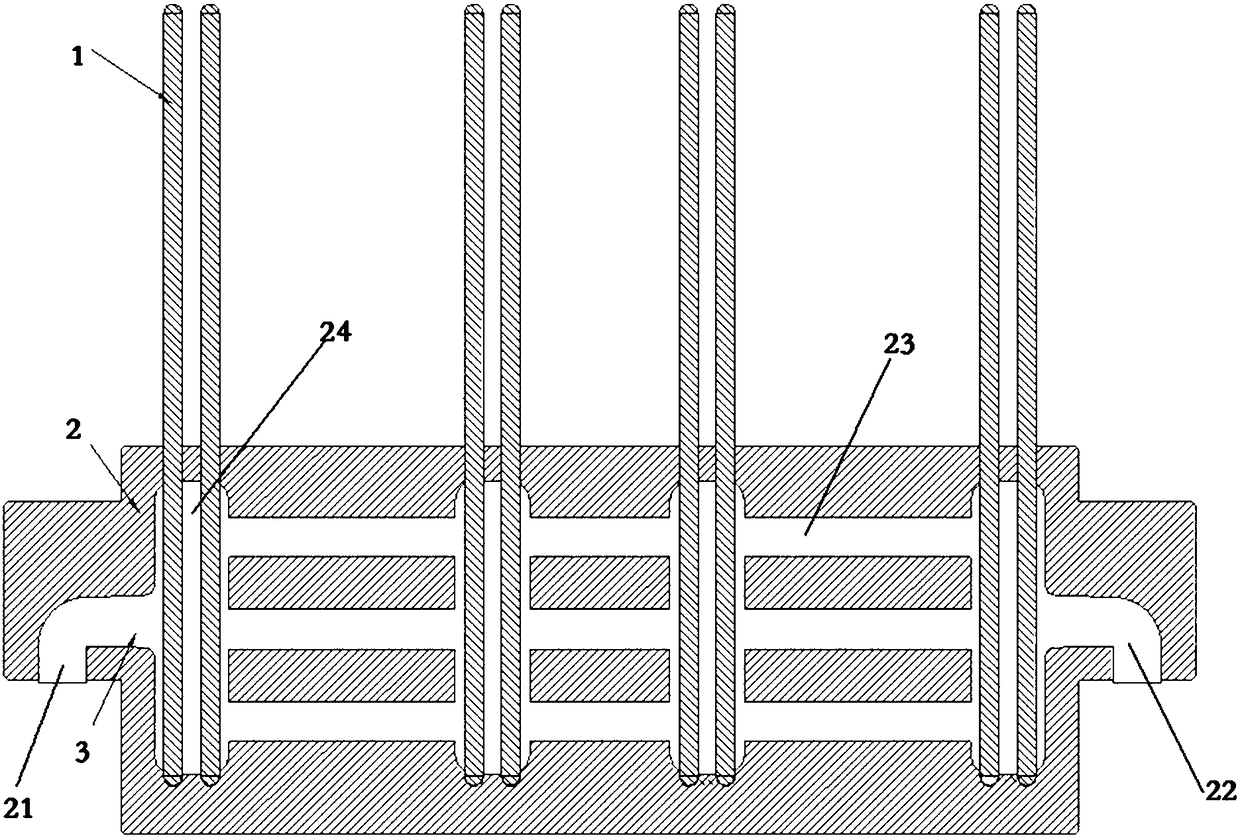
[0019] Such as figure 1 As shown, a cooling device for an injection mold of an automobile connector includes a heat exchange tube 1, a cooling water tank 2 and a cooling water 3, the cooling water 3 first enters the injection mold and then enters the cooling water tank 2, and the One end of the heat exchange tube 1 is in contact with the injection mold, and the other end is immersed in the cooling water tank 2 .

[0020] The cooling water tank 2 is a 3D p...


PUM


Abstract

The invention relates to a cooling device for an automobile connector injection mold. The cooling device comprises a heat exchange tube, a cooling water tank and cooling water, wherein the cooling water firstly enters the injection mold and then enters the cooling water tank, one end of the heat exchange tube is in contact with the injection mold, and the other end of the heat exchange tube is immersed in the cooling water tank. Compared with the prior art, the device has the advantages of being more remarkable in effect, simpler in structure, and capable of solving the problem of space limitation.

Description

technical field [0001] The invention relates to a cooling device for an injection mold, in particular to a cooling device for an injection mold of an automobile connector. Background technique [0002] At present, as an injection mold cooling system, the traditional waterway is still the most widely used cooling method. However, in some molds, especially injection molds for automotive connectors, due to limited mold space and higher production cycle requirements, the pursuit of efficiency in mold cooling systems has become increasingly prominent. The limitation of the traditional waterway is obviously to solve the problems and bottlenecks encountered in mold cooling [0003] The use of cooling exchange tubes can perfectly solve some of the problems caused by the limited mold space. However, due to the heat exchange principle of the cooling exchange tube itself, the length of the heat that needs to be taken away is one-third of the length of the cooling tube itself, and it i...

Claims


Application Information

Patent Timeline
IPC IPC(8): B29C45/73
CPCB29C45/7312
Inventor 高昌玉
Owner SHANGHAI CHIEF LAND ELECTRONICS CO LTD
Why Eureka
Try Eureka