
Vehicle heat exchange system

A technology of heat exchange system and heat exchange box, which is applied in the direction of machines/engines, generators/motors, mechanical equipment, etc., can solve the problem of insufficient utilization of the heat dissipated, and achieve simple structure, high fuel utilization efficiency, and effective output The effect of high torque

Active Publication Date: 2019-03-19
青岛永晟热交换器有限公司
View PDF10 Cites 1 Cited by
  • Summary
  • Abstract
  • Description
  • Claims
  • Application Information

AI Technical Summary

Problems solved by technology

There are some patents that combine the engine cooling system with the vehicle's lubricating oil system and heating system, but the utilization of the heat dissipated is far from enough

Method used


Image

  • Vehicle heat exchange system
  • Vehicle heat exchange system
  • Vehicle heat exchange system

Examples


Embodiment Construction

[0020] In order to make the features and advantages of the present invention more comprehensible, specific embodiments of the invention will be described in detail below in conjunction with the accompanying drawings.

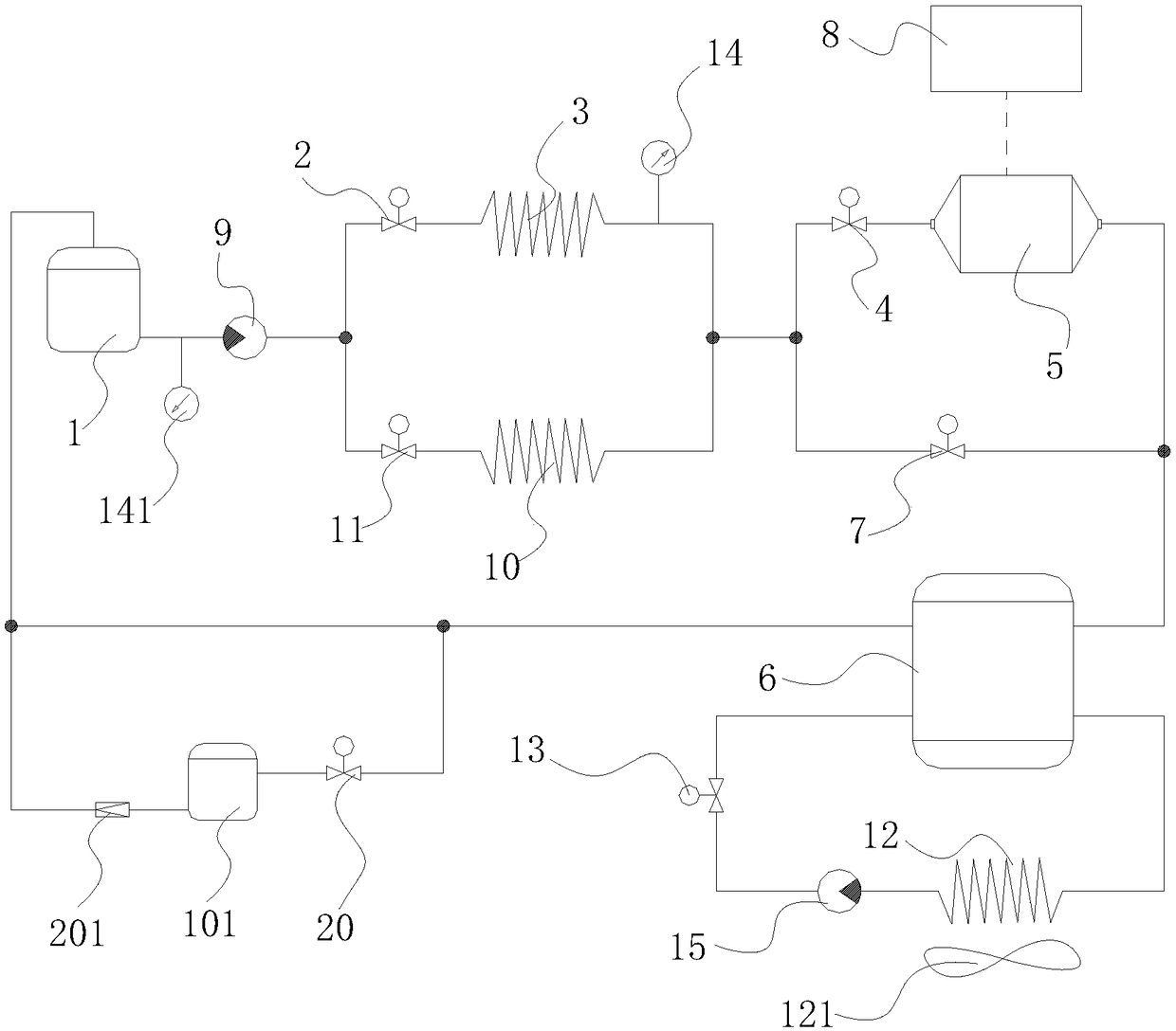
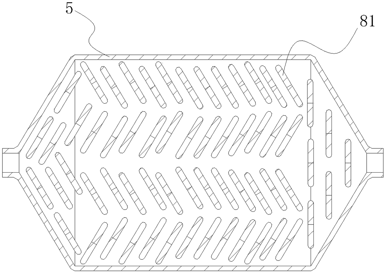
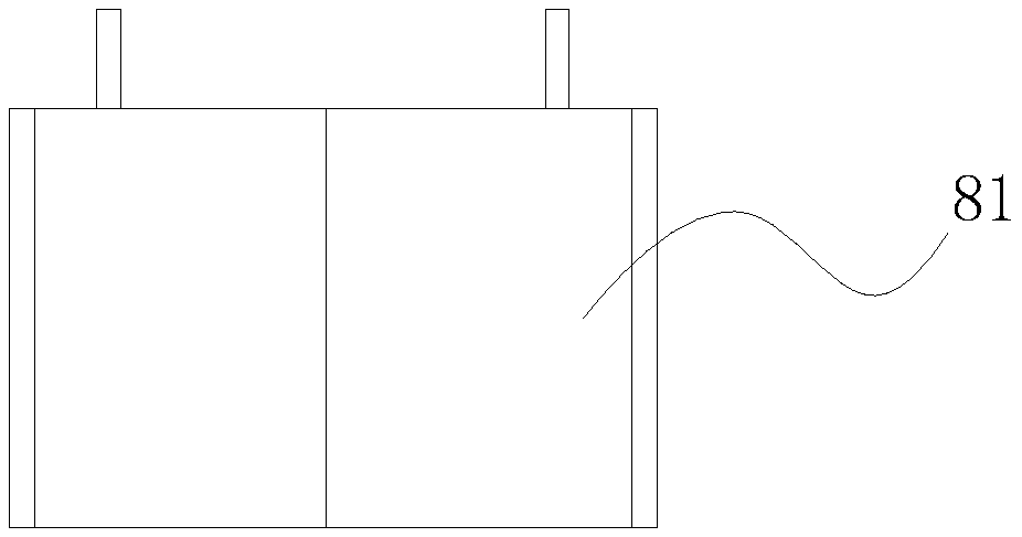
[0021] combine Figure 1~3 , a vehicle heat exchange system, including a coolant tank 1, a first electronically controlled proportional valve 2 connected to the outlet of the coolant tank 1, the coolant tank 1 is equipped with a circulating pump 9, and the first electronically controlled proportional valve The valve 2 is connected to the first cooling pipeline 3 of the engine; the first cooling pipeline 3 is connected to the heat exchange box 5 through the electronic thermometer 14 and the second electronically controlled proportional valve 4 in sequence, and the heat exchange box 5 is connected to the The heat accumulator 6 is connected, the outlet of the heat accumulator 6 is connected with the coolant tank 1, the inlet of the heat accumulator 6 is also connec...


PUM


Abstract

The invention relates to the field of vehicle heat dissipating systems, in particular to a vehicle heat exchange system. According to the adopted technical scheme, the vehicle heat exchange system comprises a cooling liquid tank and a first electric control proportional valve which is connected with an opening of the cooling liquid tank, and further comprises a thermoelectric generator, and the cooling liquid tank is matched with a circulating pump; the first electric control proportional valve is connected with an inlet of a first cooling pipeline of an engine, and the first cooling pipelinesequentially passes through an electronic thermometer and a second electric control proportional valve and then is connected with a heat exchange tank; the heat exchange tank is connected with a heataccumulator which is connected with the cooling liquid tank, and an inlet of the heat accumulator is further connected with a third electric control proportional valve; the other end of the third electric control proportional valve is directly connected with the front end of the second electric control proportional valve; the thermocouple heat end of the thermoelectric generator is mounted in theheat exchange tank, and the thermoelectric generator is connected with a vehicle power supply system through a voltage stabilizing circuit; and the whole system is controlled by an ECU to operate. Thevehicle heat exchange system has the characteristics of being high in fuel oil utilization efficiency, simple in structure, economical and environmentally friendly.

Description

technical field [0001] The invention relates to the field of vehicle cooling systems, in particular to a vehicle heat exchange system. Background technique [0002] my country has become the world's largest automobile production and sales country, and the number of automobiles is also increasing year by year. The ensuing environmental problems, energy problems and other problems continue to worsen. Energy saving and emission reduction has become the development trend of my country's automobile industry, and it is also a key measure to respond to the call of creating an "environment-friendly, resource-saving" society, which has led to the emergence of hybrid and pure electric vehicles. However, under the current situation that pure electric vehicles have insufficient battery life and the hybrid structure is complex and costly, fuel vehicles still have a huge inventory and market demand. [0003] According to survey data, the thermal efficiency of existing automobile engines ...

Claims


Application Information

Patent Timeline
Patent Type & Authority Applications(China)
IPC IPC(8): F02G5/00F01M5/02H02N11/00
CPCH02N11/002F01M5/021F02G5/00Y02T10/12
Inventor 杨骏程瑞成陶伟平
Owner 青岛永晟热交换器有限公司
Learn More