Micro-visual temperature measuring device

A temperature measuring device, miniature technology, applied in the field of temperature measuring devices, miniature visual temperature measuring devices, can solve the problems of inconvenient fixing, slow response, low precision, etc., achieve effective and correct transmission, prevent excessive temperature, design reasonable effect

Inactive Publication Date: 2019-03-19
ZHENGZHOU HAIWEI OPTOELECTRONICS TECH CO LTD
View PDF4 Cites 1 Cited by
  • Summary
  • Abstract
  • Description
  • Claims
  • Application Information

AI Technical Summary

Problems solved by technology

[0002] Thermometer is a tool for accurately measuring and judging temperature. Most thermometers are traditional thermometers. The principles of these traditional thermometers are mostly based on the principle that mercury, alcohol, water and other liquids expand when heated and contract when cooled. Due to the material and principle, these thermometers have too many limitations, such as single performance, easy damage, short life, poor reliability, large temperature package, low precision, etc. The liquid in the temperature package of expansion thermometers expands It takes a certain amount of time to shrink and shrink, so the reaction is relatively slow, and it is difficult to implement real-time measurement of temperature. With the development of technology and the advancement of materials, many electronic thermometers have appeared. These electronic thermometers are accurate and responsive, although The function is complete but the volume is relatively large, it is very inconvenient to use in some small spaces, and it is very inconvenient to fix when long-term measurement is required

Method used


Image

  • Micro-visual temperature measuring device
  • Micro-visual temperature measuring device
  • Micro-visual temperature measuring device

Examples


Embodiment Construction

[0015] The following will clearly and completely describe the technical solutions in the embodiments of the present invention with reference to the accompanying drawings in the embodiments of the present invention. Obviously, the described embodiments are only some, not all, embodiments of the present invention. Based on the embodiments of the present invention, all other embodiments obtained by persons of ordinary skill in the art without making creative efforts belong to the protection scope of the present invention.

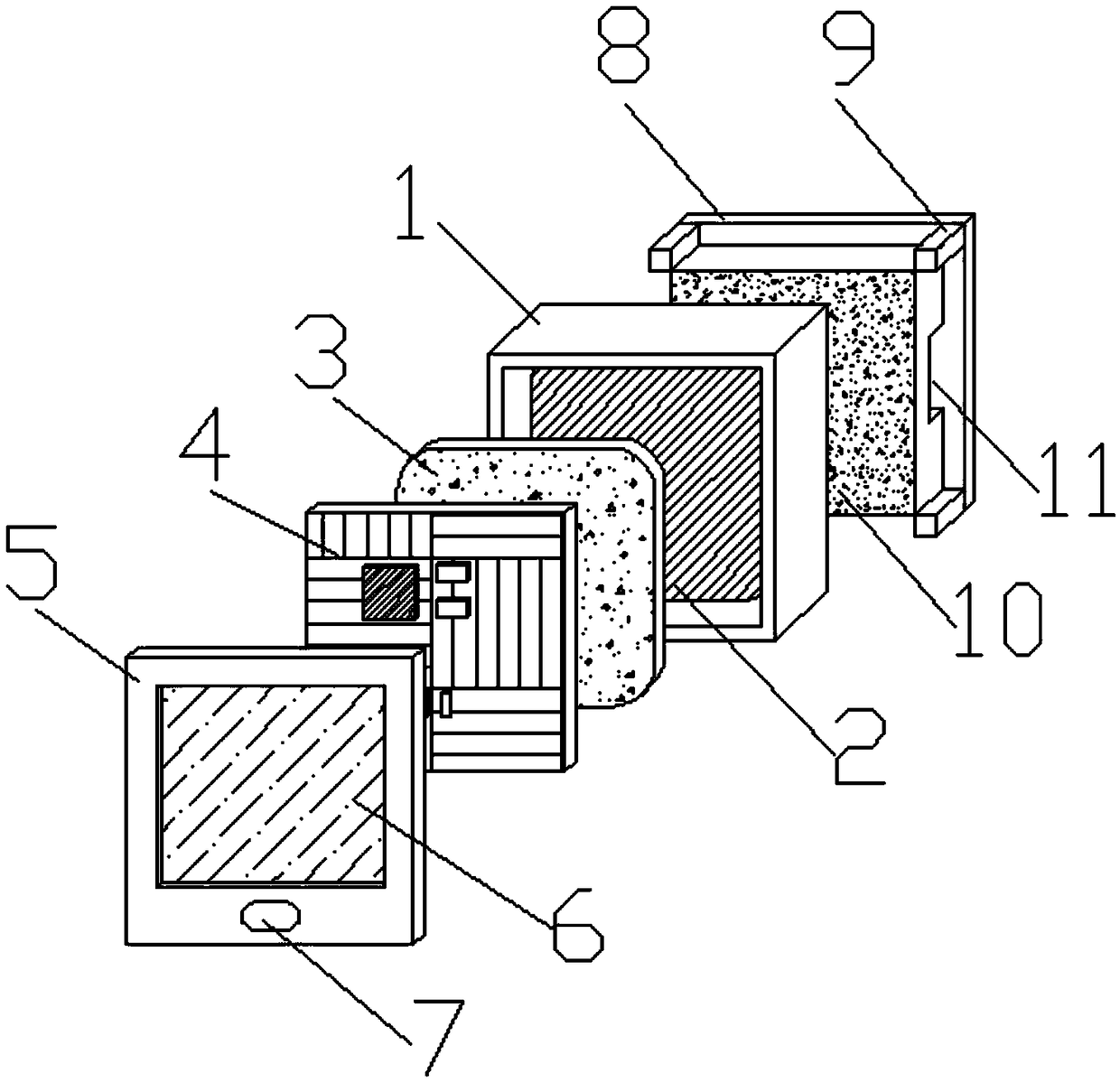
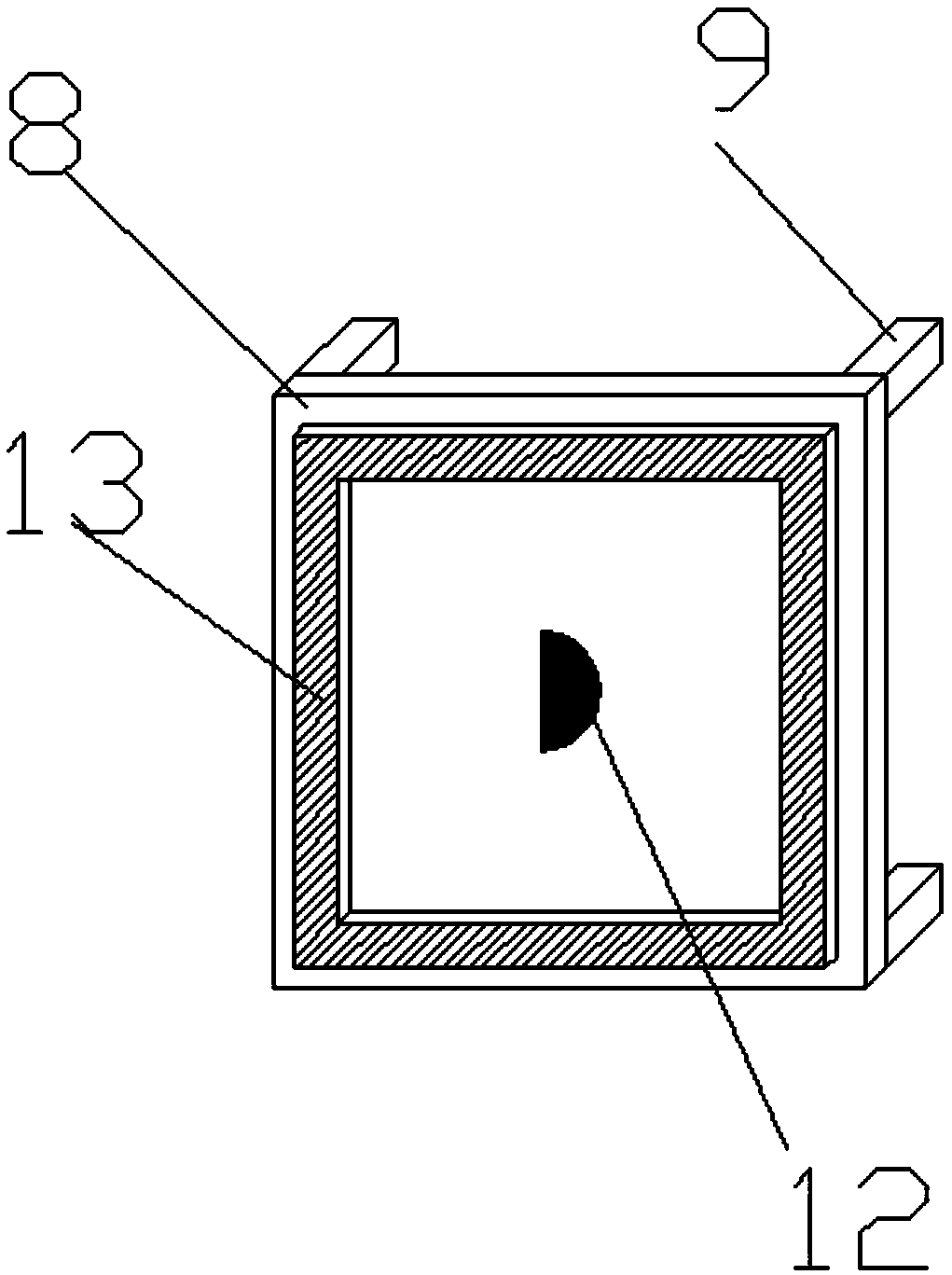
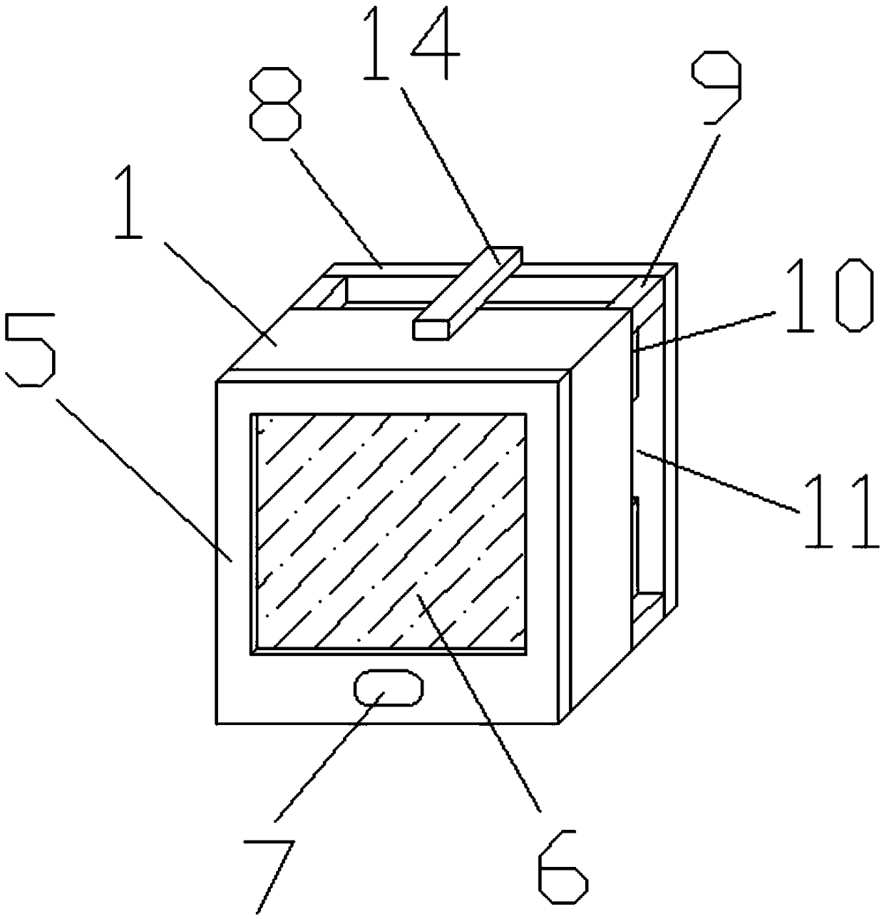
[0016] see Figure 1-3 , a miniature visual temperature measuring device, including a casing 1, a battery 2, a rubber plate 3, a circuit board 4, a panel 5, a display screen 6, buttons 7, a mounting plate 8, a support column 9, a heat insulation block 10, a fixed port 11. A sensor 12, a magnet 13 and a connecting bridge 14; a battery 2 is fixed inside the housing 1, a rubber plate 3 is fixed on the battery 2, a circuit board 4 is fixed on the rubber plate 3, a...


PUM


Abstract

The invention discloses a micro-visual temperature measuring device. The micro-visual temperature measuring device comprises a shell, a storage battery, a rubber plate, a circuit board, a panel, a display screen, a button, an installing plate, a supporting column, a heat insulation block, a fixed opening, a sensor, a magnet and a connecting bridge. The micro-visual temperature measuring device hasthe advantages that the insulation and deformable rubber plate is padded between the storage battery and the circuit board, it is avoided that the circuit board is in contact with the storage batteryto cause an insulation fault, heat generated when the circuit board works can also be isolated, and it is avoided that the temperature of the surface of the storage battery is over high; space between the shell and the installing plate is filled with the heat insulation block made from a heat insulation material, the measuring part devices are separated from the temperature displaying and information processing device parts, and it is avoided that due to the high temperature precision equipment such as the display screen and the circuit board is damaged. The micro-visual temperature measuringdevice is small and exquisite in using and convenient to check, and is particularly suitable for temperature measurement of some narrow areas.

Description

technical field [0001] The invention relates to a temperature measuring device, in particular to a miniature visible temperature measuring device, which belongs to the field of temperature measuring equipment. Background technique [0002] Thermometer is a tool for accurately measuring and judging temperature. Most thermometers are traditional thermometers. The principles of these traditional thermometers are mostly based on the principle that mercury, alcohol, water and other liquids expand when heated and contract when cooled. Due to the material and principle, these thermometers have too many limitations, such as single performance, easy damage, short life, poor reliability, large temperature package, low precision, etc. The liquid in the temperature package of expansion thermometers expands It takes a certain amount of time to shrink and shrink, so the reaction is relatively slow, and it is difficult to implement real-time measurement of temperature. With the development...

Claims


Application Information

Patent Timeline
Patent Type & Authority Applications(China)
IPC IPC(8): G01K13/00
CPCG01K13/00
Inventor 焦战威
Owner ZHENGZHOU HAIWEI OPTOELECTRONICS TECH CO LTD
Why Eureka
Try Eureka