Optical vital signs sensor

A technology of vital signs and sensors, applied in the fields of sensors, medical science, diagnosis, etc., can solve the problem that the light detector cannot be used to detect the vital signs of users.

Active Publication Date: 2019-03-19
KONINKLJIJKE PHILIPS NV
View PDF15 Cites 1 Cited by
  • Summary
  • Abstract
  • Description
  • Claims
  • Application Information

AI Technical Summary

Problems solved by technology

However, if the PPG sensor is no longer in direct contact with the user's skin, for example, if a loss of skin contact has occurred, the output of the photodetector cannot be used to detect the user's vital signs

Method used


Image

  • Optical vital signs sensor
  • Optical vital signs sensor
  • Optical vital signs sensor

Examples


Embodiment Construction

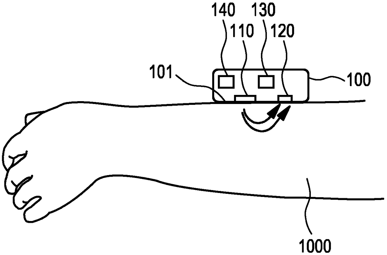
[0037] figure 1 A basic representation of the operating principle of an optical vital sign sensor is shown. exist figure 1 In , an optical vital sign sensor (eg heart rate sensor 100 ) with its contact surface 101 is arranged or placed eg on a user's arm. The contact surface 101 may be placed (directly) on the user's skin 1000 . The heart rate sensor 100 includes at least one light source 110 and at least one light detector 120 . The light source 110 emits light onto or into the skin 1000 of the user via the contact surface 101 . Some of the light is reflected, and the reflected light can be detected by the light detector 120 . Some light may be transmitted through the user's tissue and detected by photodetector 120 . Based on the reflected light, the user's vital signs, such as heart rate, can be determined.

[0038] According to the invention, pressure is applied to the small blood vessels (skin arterioles) inside the skin organ.

[0039] The optical vital sign sensor...


PUM


Abstract

An optical vital signs sensor (100) is provided, which comprises a PPG sensor (102), a force transducer (130) configured to measure a force applied via the PPG sensor (102) to a skin (1000) of the user and a processing unit (140) configured to extract information regarding a blood volume pulse from the output of the PPG sensor (102) and to map the extracted information to the blood pressure valueat a specific force applied to the PPG sensor (102).

Description

technical field [0001] The present invention relates to an optical vital sign sensor for monitoring vital signs of a user. Background technique [0002] Heart rate sensors, such as optical heart rate sensors, are known to monitor or detect vital signs, such as a user's heart rate. Such a heart rate sensor may be based on a photoplethysmographic (PPG) sensor and may be used to acquire volumetric organ measurements. With the help of a pulse oximeter, changes in the light absorption of a person's skin can be detected, and based on these measurements, the user's heart rate or other vital signs can be determined. The PPG sensor includes a light source, such as a light emitting diode (LED), that emits light into the user's skin. The emitted light is scattered in the skin and at least partially absorbed by the blood. Part of the light exits the skin and can be captured by a light detector. The amount of light captured by the light detector may be an indication of blood volume w...

Claims


Application Information

Patent Timeline
Patent Type & Authority Applications(China)
IPC IPC(8): A61B5/00A61B5/024A61B5/0225
CPCA61B5/6843A61B5/02255A61B5/02416A61B5/681A61B5/6824
Inventor J·H·格利森R·希尔比希A·希尔格斯M·G·拉达K·T·J·德格罗特R·哈克玛
Owner KONINKLJIJKE PHILIPS NV
Why Eureka
Try Eureka