Special pushing device for completely degradable occluder and method for connection of special pushing device with occluder

A technology of pushing device and occluder, which is applied in the field of medical devices or

Inactive Publication Date: 2019-03-22
SHANGHAI SHAPE MEMORY ALLOY
View PDF14 Cites 3 Cited by
  • Summary
  • Abstract
  • Description
  • Claims
  • Application Information

AI Technical Summary

Problems solved by technology

[0011] The technical problem to be solved by the present invention is: solve the p...

Method used


Image

  • Special pushing device for completely degradable occluder and method for connection of special pushing device with occluder
  • Special pushing device for completely degradable occluder and method for connection of special pushing device with occluder
  • Special pushing device for completely degradable occluder and method for connection of special pushing device with occluder

Examples


Embodiment 1

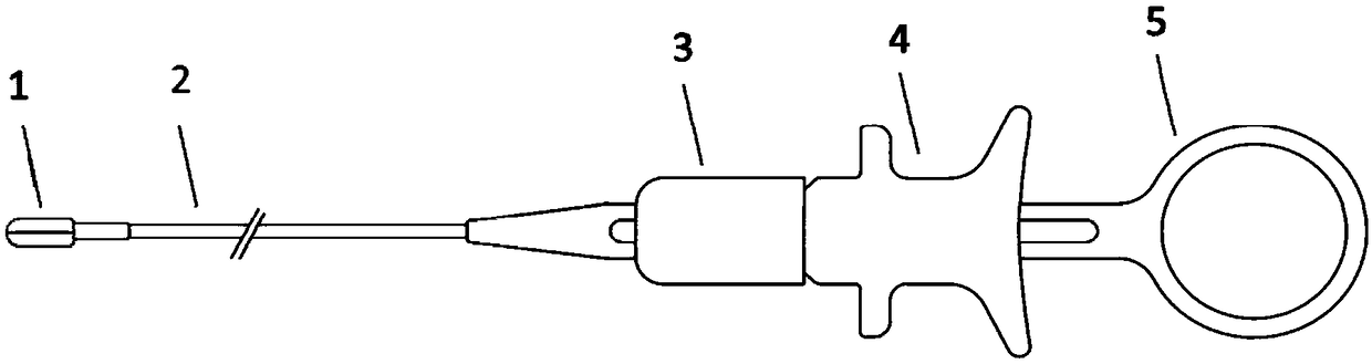
[0043] A special pushing device for a fully degradable occluder, such as Figure 2a As shown, it includes a push cable 2 and a handle, and the push cable 2 includes a clamp head 1, a spring cable 7 and an inner core wire 6; the handle includes a push ring 5, a slider 4 and a locking member 3.

[0044] The spring steel cable 7 is provided with an inner core wire 6 that can move back and forth, the front end of the spring steel cable 7 is fixedly connected with the middle position of the clamp head 1, the rear end of the clamp head 1 is connected with the front end of the inner core wire 6, and the inner core wire The rear end of 6 is connected with slide block 4, and slide block 4 is enclosed within on the push ring 5, and the push ring 5 is also covered with locking part 3, and the spring steel cable 7 is located in the push ring 5.

[0045] The pliers head is designed as two encircling clips, such as Figure 2b As shown, a circular arc-shaped top is formed after merging, and...

Embodiment 2

[0061] In this embodiment, the pliers head 1 has a rattooth (two-tooth) structure, and the pliers head 1 includes two clips that are staggered from each other, and each clip is a rattooth ("L" shape) structure, such as Figure 4a-Figure 4c As shown, the upper end of the "L"-shaped structural clip is connected to the front end of the spring steel cable 7, and the lower end of the "L"-shaped structural clip is connected to the front end of the inner core wire 6. The clamp head of this design has no special requirements on the structure of the welded part of the occluder, for example, the surface is rough (no roughness is required, or roughness does not affect the function of the clamp head), and even the occluder can have no tail. Grasp the bottom of the right disk of the occluder with two rat teeth to pull the occluder into the sheath.

[0062] Others are the same as in Example 1.

Embodiment 3

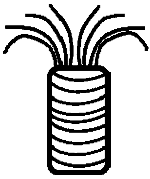
[0064] Such as Figure 5a , Figure 5b As shown, the clamp head 1 is a double-layer rope 8, and the two ends of the double-layer rope 8 are fixed on the front end of the spring steel cable 7, and the inner core wire 6 passes through the hole formed in the middle of the double-layer rope 8. In the middle of the spring steel cable 7 is a slidable inner core wire 6, and the slide block on the handle can adjust the expansion and contraction of the inner core wire 6. Specifically, push the slide block forward, the inner core wire 6 stretches out forward, slide the slide block backward, and the inner core wire 6 retracts backward. The two ends of double-layer rope 8 all are fixed on the same position (being in the groove 9) of the head end of spring steel cable 7. When the double-layer rope 8 is in use, it passes through the double-headed rivetless or single-rivet degradable occluder without the rivet end, and the inner core wire 6 must pass through the middle of the double-layer ...


PUM


Abstract

The invention discloses a special pushing device for a completely degradable occluder. The special pushing device is characterized by comprising a spring steel cable, an inner core wire capable of moving back and forth is arranged in the spring steel cable, the front end of the spring steel cable is fixedly connected to the middle of a forcep head, the rear end of the forcep head is connected withthe front end of the inner core wire, the rear end of the inner core wire is connected with a slider which sleeves a pushing ring, a locking part sleeves the pushing ring, and the spring steel cableis arranged in the pushing ring. The joint position of the middle of the forcep head and the occluder is provided with a through hole, or the forcep head is a double-layer sleeve rope, or the forcep head is in a mouse tooth structure. The special pushing device is fittingly connected with the occluder and used with the occluder to solve problems of pulling the completely degradable occluder into asheath, pushing, releasing and the like in an interventional operation from the engineering point of view, and safety and effectiveness in application to transthoracic and percutaneous interventionalsurgeries.

Description

technical field [0001] The invention relates to a medical device for minimally invasive interventional surgery, in particular to a special pushing device for a fully degradable occluder, which belongs to the field of medical device technology. Background technique [0002] The current main treatments for patients with congenital heart disease are surgical thoracotomy and percutaneous interventional surgery. Surgical thoracotomy uses patch repair or simple suture to repair heart defects. Percutaneous interventional surgery is to implant NiTi alloy seals under X-ray imaging. Occluder, to seal the defect. With the development of science and technology, minimally invasive surgical transthoracic surgery has become a new hybrid surgical method that combines the advantages of both surgical external thoracic and percutaneous intervention. That is to say, the large trauma of surgical thoracotomy is avoided, and the radiation of X-rays is also avoided. The implantation of the NiTi oc...

Claims


Application Information

Patent Timeline
IPC IPC(8): A61B17/00A61B17/12
CPCA61B17/0057A61B17/12109A61B17/12122A61B2017/1205A61B2017/00575A61B2017/00831A61B2017/00623
Inventor 曾凡艳丁正杨永森耿聪颖李博陈娟蒲忠杰
Owner SHANGHAI SHAPE MEMORY ALLOY
Why Eureka
Try Eureka