Multi-tooth positioning hydraulic rotary workbench

A technology of rotary workbench and workbench, which is applied in the field of automobile manufacturing, and can solve problems such as difficulty in ensuring precision, easy deformation, and low production efficiency.

Pending Publication Date: 2020-10-27
CHANGZHOU VOCATIONAL INST OF ENG
View PDF0 Cites 0 Cited by
  • Summary
  • Abstract
  • Description
  • Claims
  • Application Information

AI Technical Summary

Problems solved by technology

Traditional processing requires multiple clamping, easy deformation during processing, difficult to guarantee accuracy, and low efficiency in mass production

Method used


Image

  • Multi-tooth positioning hydraulic rotary workbench
  • Multi-tooth positioning hydraulic rotary workbench
  • Multi-tooth positioning hydraulic rotary workbench

Examples


Embodiment Construction

[0017] The present invention will be described in detail below in conjunction with the accompanying drawings and specific embodiments.

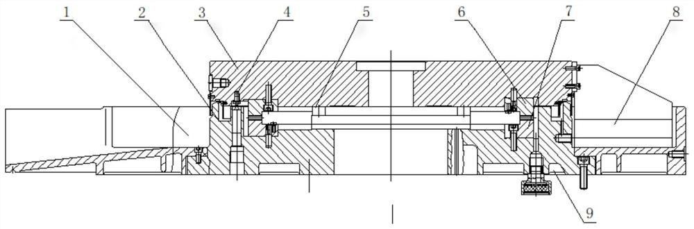
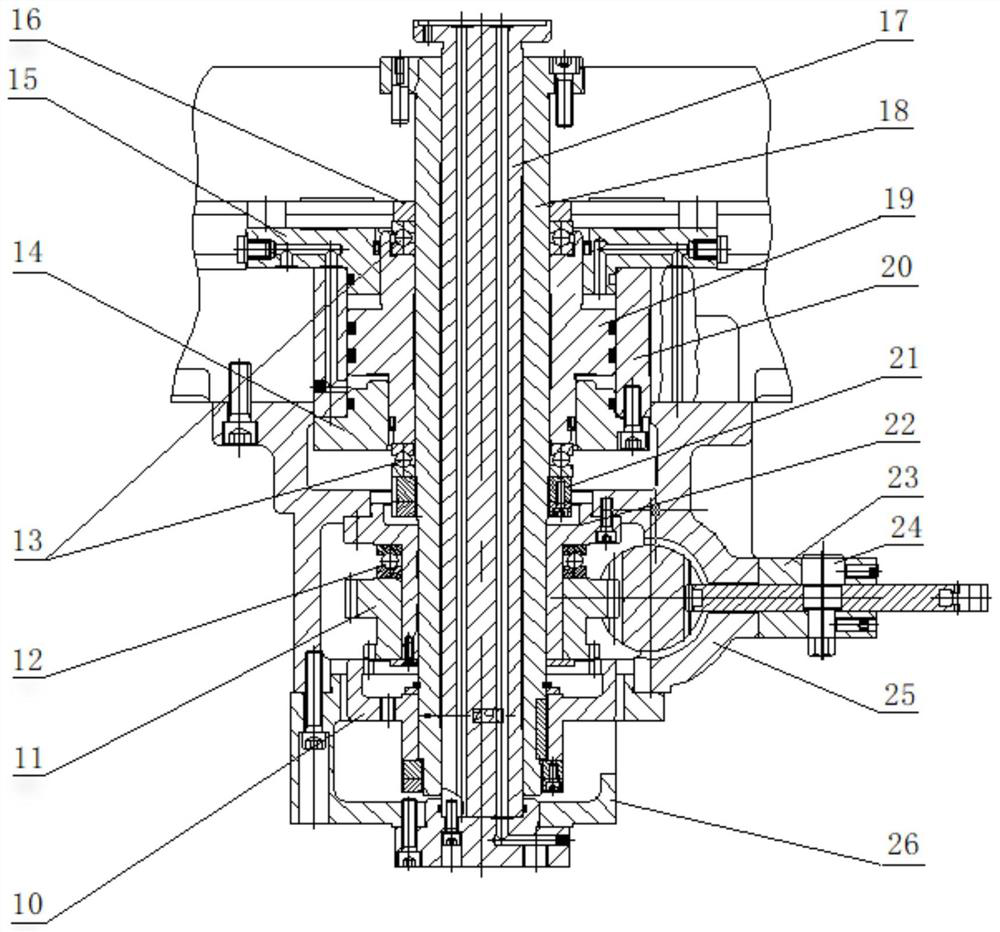
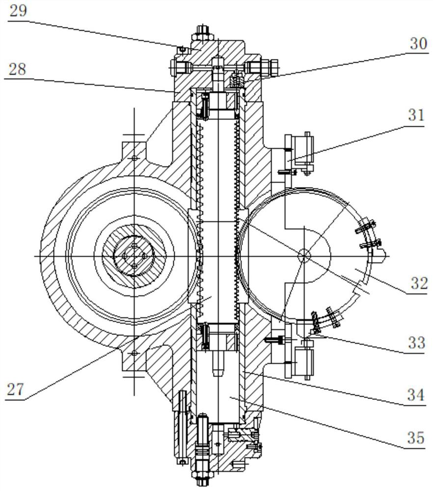
[0018] Such as Figure 1-3 As shown in the figure, a multi-tooth positioning hydraulic rotary table includes a worktable, a base, a clamping hydraulic cylinder, an indexing hydraulic cylinder and a Hirth plate. The positioning method of the multi-tooth positioning rotary table is Hirth Type positioning, using the disengagement and meshing of the precision upper and lower toothed discs to perform interval indexing, and hydraulically driving the rack shaft to drive the indexing and rotation of the empty sleeve and the rotary shaft. When the worktable is lifted, the stroke of the rack is controlled. Realize the indexing of different positions; the upper and lower toothed discs are in a clamped state when working.

[0019] The workbench is a disc, on which the machine tool clamps are installed, and a hydraulic clamping distributor is installed i...


PUM


Abstract

The invention discloses a multi-tooth positioning hydraulic rotary workbench. The multi-tooth positioning hydraulic rotary workbench comprises a workbench, a base, a clamping hydraulic cylinder, an indexing hydraulic cylinder and a mouse tooth plate, wherein the positioning mode of the multi-tooth positioning hydraulic rotary workbench is a mouse tooth plate positioning, the disengagement and meshing of the precision upper and lower gear plates are used for interval indexing, and a hydraulical drive rack shaft drives an empty sleeve and a rotating position on a rotary shaft to rotate; when theworkbench is raised, a rack stroke is controlled, and the rotating position with different workstations is realized; during working, the upper and lower gear plates are in a clamping state; and the multi-tooth positioning hydraulic rotary workbench improves the production efficiency, has a long service life, and higher processing accuracy.

Description

technical field [0001] The invention relates to the technical field of automobile manufacturing, in particular to a multi-tooth positioning hydraulic rotary worktable. Background technique [0002] The connecting rod is one of the main transmission parts in the automobile engine, which mainly transmits the expansion pressure acting on the top surface of the piston to the crankshaft, and is driven by the crankshaft to drive the piston to compress the gas in the cylinder. The connecting rod bears a sharply changing dynamic load during work, so the dimensional accuracy and shape accuracy of the large and small head holes of the connecting rod must be guaranteed during the machining process. In traditional processing, multiple clamping is required, it is easy to deform during processing, the accuracy is difficult to be guaranteed, and the efficiency of mass production is low. [0003] In order to meet the production needs of large quantities of parts and improve production effi...

Claims


Application Information

Patent Timeline
Patent Type & Authority Applications(China)
IPC IPC(8): B23Q16/06
CPCB23Q16/06
Inventor 金燕王传旭陆海林
Owner CHANGZHOU VOCATIONAL INST OF ENG
Why Eureka
Try Eureka