Numerical control rack gear milling machine

A technology of gear milling machine and rack, which is applied in the field of CNC rack gear milling machine to achieve the effect of reducing cost, improving competitiveness and low labor intensity

Inactive Publication Date: 2009-09-09
徐国金
View PDF0 Cites 4 Cited by
  • Summary
  • Abstract
  • Description
  • Claims
  • Application Information

AI Technical Summary

Problems solved by technology

[0003] The technical problem to be solved by the invention is: aiming at the above shortcomings of the same kind of machine tools of many domestic manufacturers at present, to provide a kind of indexing which utilizes a numerical control system, cooperates with a servo motor and a high-precision ball screw, and the indexing accuracy is better than that of the existing rack. CNC rack gear milling machine with significantly improved machine, automatic cutting, automatic indexing, and low labor intensity

Method used


Image

  • Numerical control rack gear milling machine
  • Numerical control rack gear milling machine
  • Numerical control rack gear milling machine

Examples


Embodiment Construction

[0013] The present invention is described in conjunction with accompanying drawing.

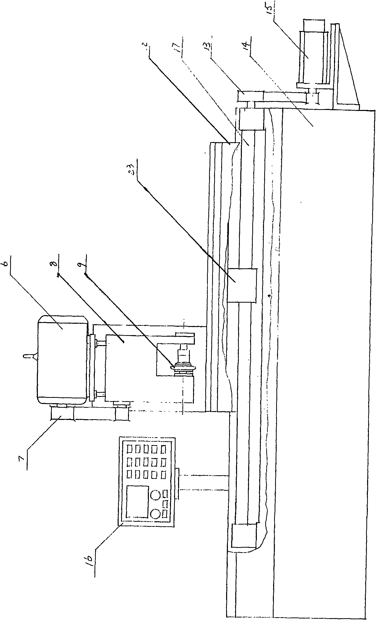
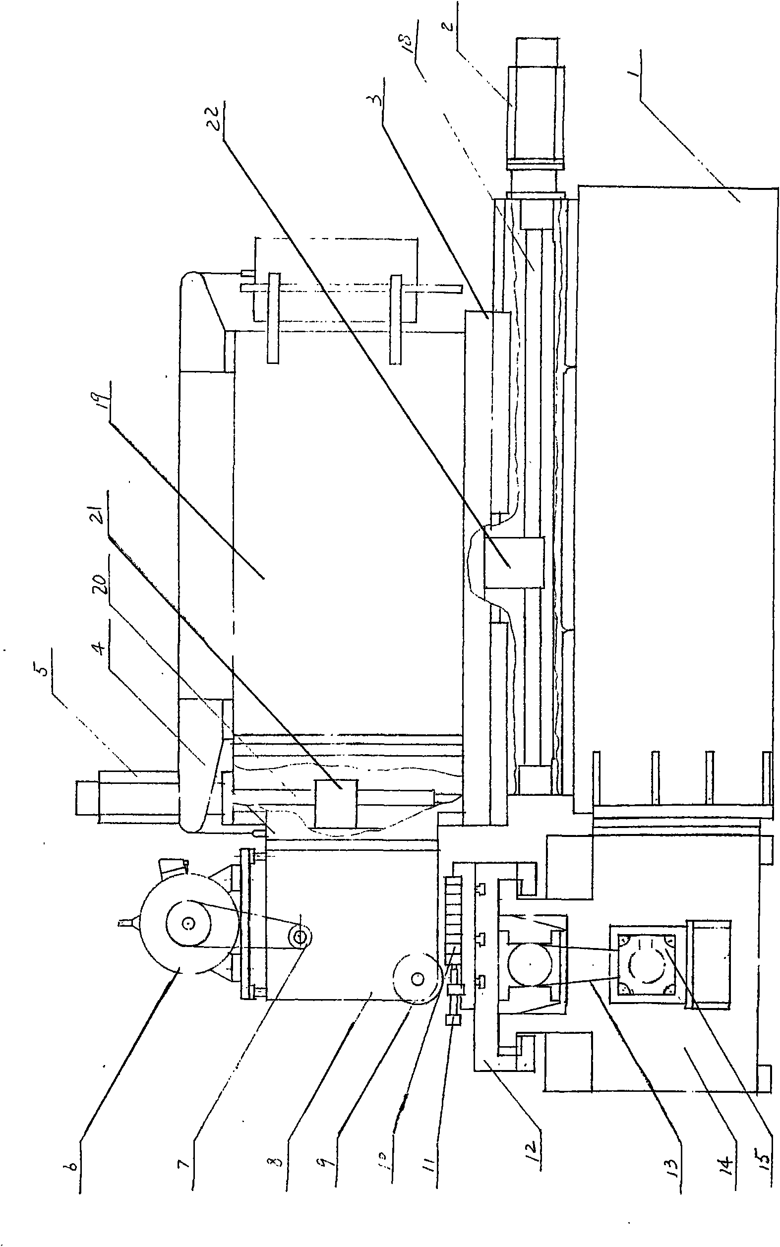
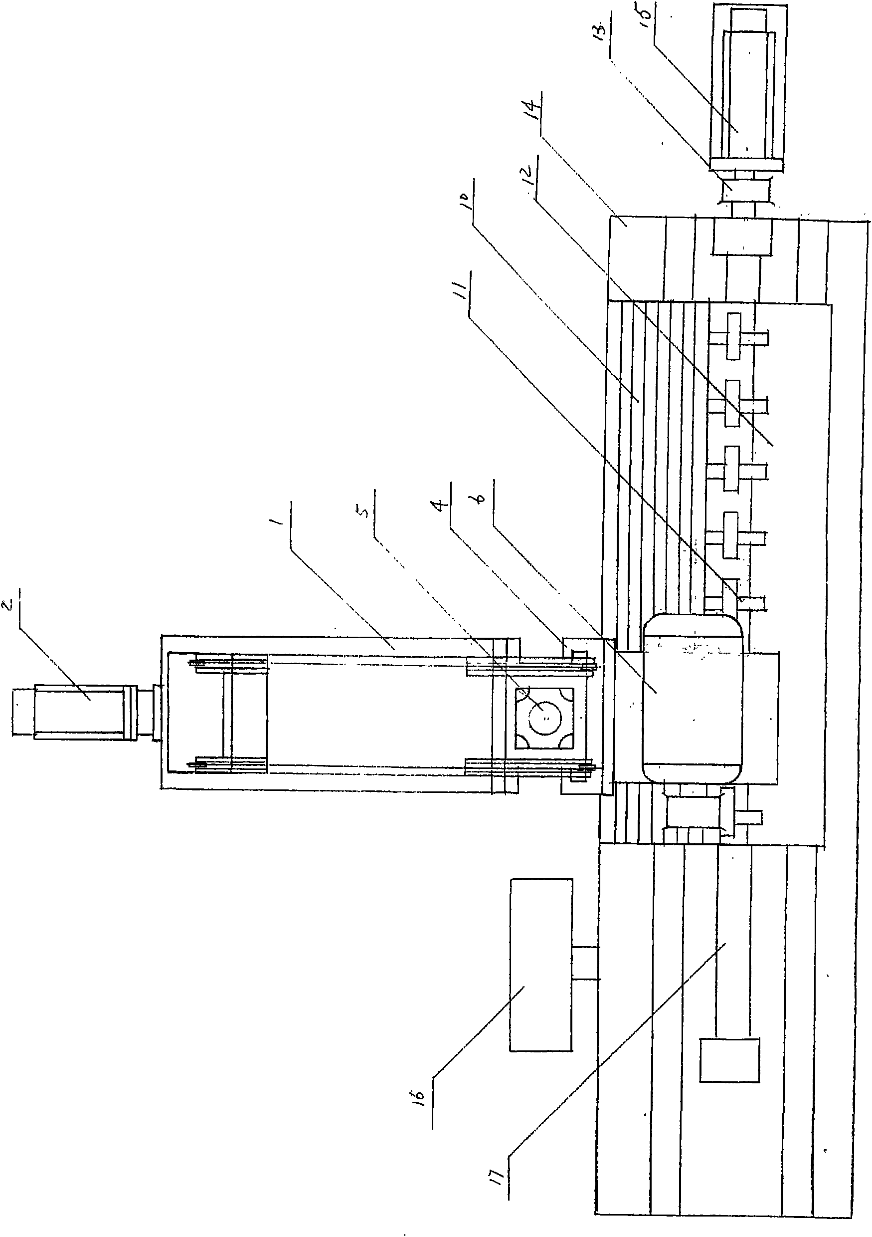
[0014] A CNC rack gear milling machine, including a Z-direction bed 1, a Z-direction servo motor 2, a Z-direction carriage 3, a Y-direction small carriage 4, a Y-direction servo motor 5, a frequency conversion speed regulation motor 6, and a synchronous toothed belt Wheel 7, cutter shaft box 8, milling cutter 9, compression screw 11, X-direction large carriage 12, X-direction synchronous rack pulley 13, X-direction bed 14, X-direction servo motor 15, CNC system 16, X direction ball screw 17, Z direction ball screw 18, support 19, Y direction ball screw 20, Y direction ball screw nut 21, Y direction ball screw nut 22 and X direction ball screw nut 23 nuts.

[0015] The Z-direction bed 1 and the X-direction bed 14 are spliced ​​into a T-shape, and the X-direction large carriage 12 is movably installed above the X-direction bed 14 (the X-direction large carriage 12 can be indexed and moved left ...


PUM


Abstract

The invention relates to a numerical control rack gear milling machine. A Z-direction tool body (1) and an X-direction tool body (14) are spliced into a T shape, and a large X-direction dragging plate (12) is movably arranged above the X-direction tool body (14). An X-direction roll ball screw rod (17) is arranged in the X-direction tool body (14), and an X-direction servo motor (15) is arranged on the right side of the X-direction tool body (14). An X-direction synchronous rack belt wheel (13) is connected between the X-direction servo motor (15) and the X-direction roll ball screw rod (17), and an X-direction roll ball screw rod nut (23) is fixedly arranged on the large X-direction dragging plate (12), and the X-direction roll ball screw rod nut (23) can move left and right on the X-direction roll ball screw rod (17). A press screw nail (11) is arranged above the large X-direction dragging plate (12), and parts such as a Z-direction dragging plate (3), a small Y-direction dragging plate (4), and the like are arranged in the mode similar to that of the parts in the X direction. A numerical control system (16) is fixedly arranged on the tool body (14). Compared with the prior rack machine, the numerical control rack gear milling machine obviously improves the indexing accuracy, has the advantages of automatic cutting, automatic indexing and low labor intensity, and greatly saves the labor cost.

Description

technical field [0001] The invention relates to a gear milling machine, in particular to a numerically controlled rack gear milling machine. Background technique [0002] The existing rack machine is transformed from a milling machine. According to the racks of different modulus, the ratio of the hanging wheels is calculated, and the indexing is driven by the hanging wheels. The labor intensity is high, the efficiency is low, the indexing accuracy is poor, and the processing length is limited. . At present, the diameter of milling cutters of similar machine tools of many domestic manufacturers is about 180 mm, which not only increases the difficulty of cutting, but also increases the cost of using the cutters. Contents of the invention [0003] The technical problem to be solved by the invention is: aiming at the above shortcomings of the same kind of machine tools of many domestic manufacturers at present, to provide a kind of indexing which utilizes a numerical control ...

Claims


Application Information

Patent Timeline
Patent Type & Authority Applications(China)
IPC IPC(8): B23F23/08B23F5/26G05B19/18
Inventor 徐国金
Owner 徐国金
Why Eureka
Try Eureka