Multifacet drill boring device and machining method utilizing same
A drilling device and group drilling technology, used in boring/drilling, metal processing equipment, drilling/drilling equipment, etc., can solve the problems of downtime, loading and unloading workpieces occupying processing time, etc., to achieve high indexing accuracy, The effect of improving machining accuracy and saving machining time
- Summary
- Abstract
- Description
- Claims
- Application Information
AI Technical Summary
Problems solved by technology
Method used
Image
Examples
Embodiment 1
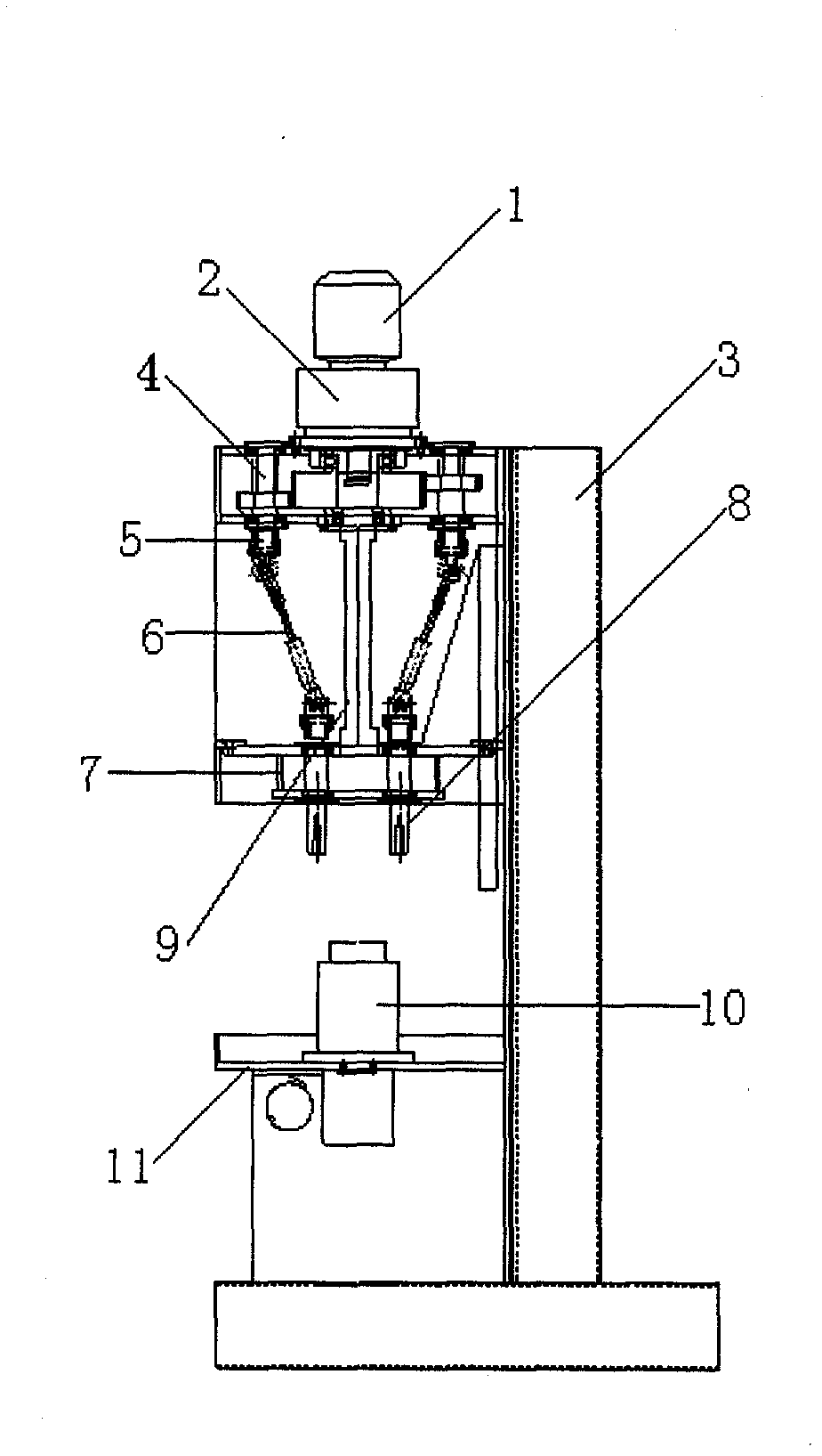
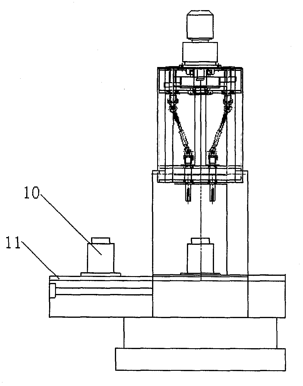
[0023] Such as figure 1 As shown, the device includes a horizontally movable two-station workbench 11, on which a workpiece fixture 10 is provided corresponding to each station. A drilling mechanism is arranged above the workbench, and the drilling mechanism and the frame 3 are fixed. The drilling mechanism includes a driving mechanism composed of a motor 1 and a reduction box 2, and also includes a plurality of power output shafts 4 driven by the driving mechanism. There may be 3-14 power output shafts. In this embodiment, 5 power output shafts are included. axis. Each power output shaft connects drill rod 8 through transmission mechanism, and the top of drill rod is positioned at drill rod box 7, and drill rod end connects drill bit or screw tap according to processing requirement. The aforementioned transmission mechanism includes a universal joint 5 and a transmission shaft 6, each power output shaft is connected to the universal joint, the universal joint is connected t...
Embodiment 2
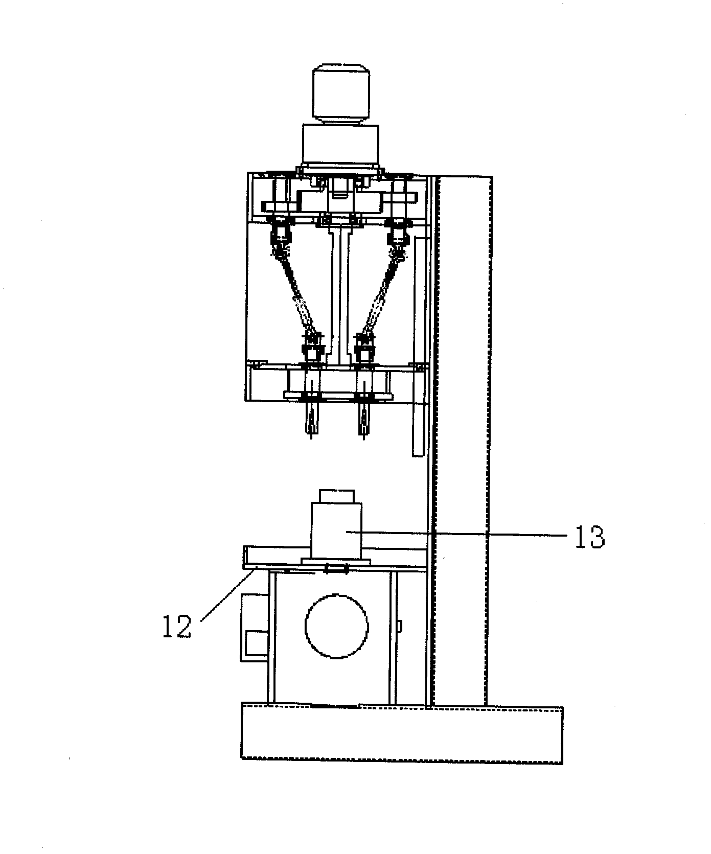
[0026] Such as image 3 As shown, the difference between the second embodiment and the first embodiment is that the workbench 12 is a horizontally rotatable multi-station workbench, and the rest of the structure is the same as that of the first embodiment.
[0027] During processing, the workpiece is loaded on the workpiece fixture 13 on the workbench, and according to the processing requirements, a drill bit or a screw tap is installed on the drill rod, and the motor is started to make a plurality of drill rods rotate simultaneously, and the workpiece is drilled. Drilling of a workpiece is performed at one station, and loading and unloading of other workpieces can be performed at the remaining stations.
Embodiment 3
[0029] Such as Figure 4 As shown, the workbench 14 of the third embodiment is a horizontally rotatable multi-station workbench, corresponding to multiple stations, and a plurality of drilling mechanisms are arranged above the workbench, and the structure of each drilling mechanism is the same as that of the first, Two drilling mechanisms are the same.
[0030] During processing, the workpiece is loaded on the workpiece fixture 15 on the workbench, and according to the processing requirements, a drill bit or a screw tap is installed on the drill rod, and the motor is started to make a plurality of drill rods rotate simultaneously, and the workpiece is drilled. After the workpiece is drilled at one station, the workpiece is rotated to the next station for the next process of drilling.
PUM
 Abstract
Description
Claims
Application Information
 - R&D
- Intellectual Property
- Life Sciences
- Materials
- Tech Scout
- Unparalleled Data Quality
- Higher Quality Content
- 60% Fewer Hallucinations
Browse by: Latest US Patents, China's latest patents, Technical Efficacy Thesaurus, Application Domain, Technology Topic, Popular Technical Reports.
© 2025 PatSnap. All rights reserved.Legal|Privacy policy|Modern Slavery Act Transparency Statement|Sitemap|About US| Contact US: help@patsnap.com


