Machine tool spindle head

A technology of working machinery and spindle head, which is applied in the direction of metal processing machinery parts, manufacturing tools, machine tool parts, etc., can solve the problems of reducing the transmission speed, vibration of the spindle unit, and reduction of machining accuracy, and prevents it from entering the gap between the spindle unit and the support head. time, maintain processing accuracy, and improve the effect of holding force

Inactive Publication Date: 2010-08-11
杉山明 +1
View PDF1 Cites 4 Cited by
  • Summary
  • Abstract
  • Description
  • Claims
  • Application Information

AI Technical Summary

Problems solved by technology

[0006] However, in the structure in which the DD motor is arranged in each yoke, the dimension in the A-axis direction of the spindle head becomes large, and the overall size of the device is increased.
If the overall size of the device is increased, for example, the internal processing of the hole formed in the workpiece, etc., due to the interference between the support head and the workpiece, it cannot cope with such processing, and the processing application is limited.
[0007] In addition, in order to reduce the interference between the support head and the workpiece, the front end of the spindle unit protrudes greatly from the support head. In this case, the distance from the axis center of the support shaft to the tool tip becomes longer. Under the influence of the load, the spindle unit vibrates during machining and the machining accuracy decreases.
Therefore, it is impossible to cope with heavy cutting, or the transmission speed must be reduced. In this case, machining is limited.
[0008] In addition, when the two drive motors (DD motors) are started, operated, and stopped, both rotations must be driven completely synchronously, which complicates the control of the drive motors (DD motors).

Method used


Image

  • Machine tool spindle head
  • Machine tool spindle head
  • Machine tool spindle head

Examples


Embodiment Construction

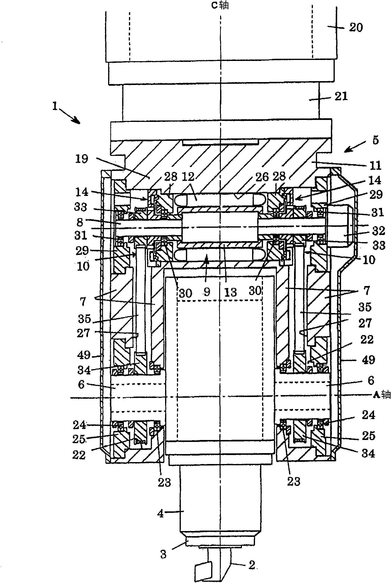
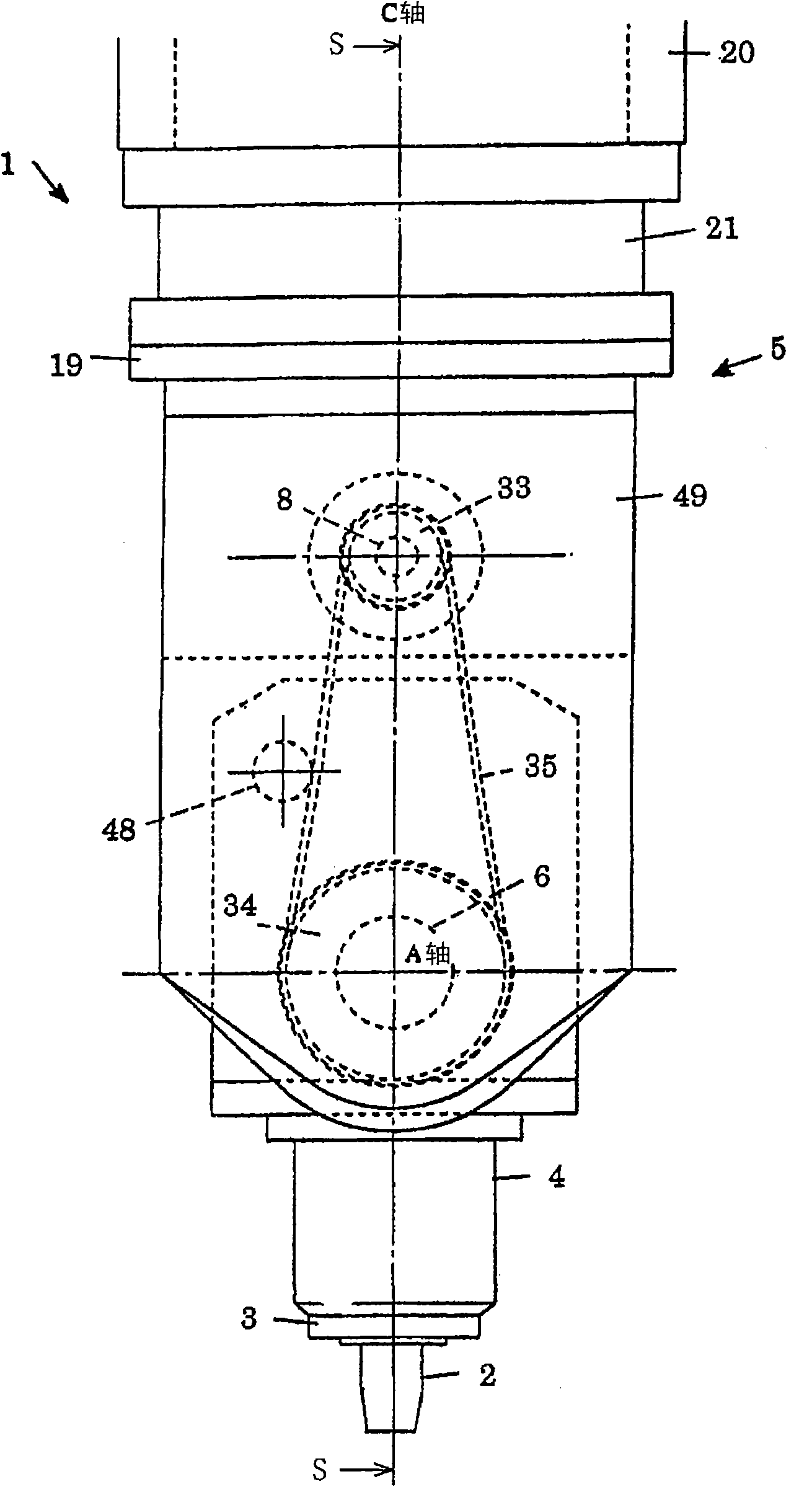
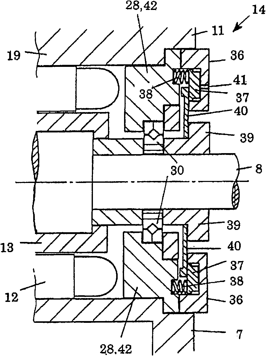
[0060] Figure 1 to Figure 3 It shows the structure of the machine tool spindle head 1 which concerns on the typical embodiment of this invention. In these Figure 1 to Figure 3 Among them, a machine tool spindle head 1 includes a spindle unit 4 that rotatably drives a spindle 3 , and a support head 5 that supports the spindle unit 4 so as to be rotatable.

[0061] Although not shown, the spindle unit 4 is a built-in motor type having a spindle motor built therein, and the spindle 3 is driven to rotate by the spindle motor. During cutting, a tool 2 suitable for cutting is attached to the front end of the main shaft 3, and the main shaft 3 is rotated by the cutting of the tool 2 to apply cutting processing to a workpiece to be processed.

[0062] The support head 5 is constituted by a fork-shaped housing 11 having a pair of left and right fork arms 7 , and the housing 11 is mounted with its mounting base 19 positioned on the C-axis portion 21 of the C-axis driving unit 20 . ...


PUM


Abstract

A machine tool spindle head which is constructed in compact size and in which a motor can be controlled easier than in conventional devices. The spindle head (1) includes a spindle unit (4) for rotationally driving a spindle (3) on the head of which a tool (2) is installed, and also includes a fork-shaped support head (5) having a pair of fork arms (7) respectively rotatably supporting a pair of support shafts (6) for supporting the spindle unit (4). The spindle head (1) further has a drive shaft (8) rotatably supported in the support head (5) and extending parallel to the direction of the axis of the support shafts (6), a drive motor (9) for rotationally driving the drive shaft (8), and a pair of drive transmission mechanisms (10) each interconnecting each of opposite ends of the drive shaft (8) and each of the support shafts (6) and transmitting rotation of the drive motor (9) to the support shafts (6).

Description

technical field [0001] The present invention relates to a spindle head for machine tools, and more particularly to a structure for rotationally driving a spindle unit. Background technique [0002] In machine tools that perform cutting of a workpiece with a rotationally driven tool, there are known a spindle unit including a built-in drive motor that rotationally drives the spindle on which the tool is to be attached to the front end, and This spindle unit is supported via a support shaft, and the spindle unit is driven to rotate around the axis (A axis) of the support shaft to index the angular position of the spindle head system for machine tools. [0003] As a spindle head similar to the above, there is a structure described in Patent Document 1. According to the spindle head of Patent Document 1, the support head is configured in a fork shape by a pair of fork-shaped arms for supporting the spindle unit, and in each fork-shaped arm, the support head connected to each si...

Claims


Application Information

Patent Timeline
Patent Type & Authority Applications(China)
IPC IPC(8): B23Q1/52B23Q1/70B23Q1/28
CPCB23Q2220/006B23Q1/5406B23Q16/025Y10T409/307672B23Q16/105
Inventor 杉山明辰田好教
Owner 杉山明
Why Eureka
Try Eureka