Slurry clarification device

A clarification device and slurry technology, applied in the direction of filtration and separation, separation methods, chemical instruments and methods, etc., can solve the problems of large slurry pool, slow settling speed, low production efficiency, etc., achieve good separation effect and improve settling efficiency , The effect of high solid-liquid separation efficiency

Active Publication Date: 2019-03-22
湖南昌迅科技环保股份有限公司
View PDF5 Cites 3 Cited by
  • Summary
  • Abstract
  • Description
  • Claims
  • Application Information

AI Technical Summary

Problems solved by technology

[0003] At present, the liquid-solid separation of slurry mainly adopts the natural sedimentation method, and the natural sedimentation process needs to stand still for a long time, especially for the slurry with a small particle size distribution, the sedimentation speed is slow, a large slurry tank is required, and the production efficiency is low

Method used


Image

  • Slurry clarification device
  • Slurry clarification device
  • Slurry clarification device

Examples


Embodiment Construction

[0031] In order to enable those skilled in the art to better understand the technical solutions in the embodiments of the present invention, and to make the above-mentioned purpose, features and advantages of the present invention more obvious and understandable, the specific implementation of the present invention will be further described below in conjunction with the accompanying drawings illustrate.

[0032] It should be noted here that the descriptions of these embodiments are used to help understand the present invention, but are not intended to limit the present invention. In addition, the technical features involved in the various embodiments of the present invention described below may be combined with each other as long as they do not conflict with each other.

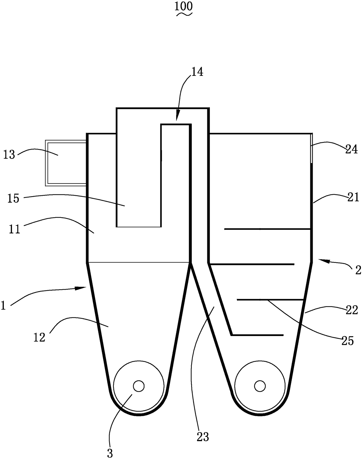
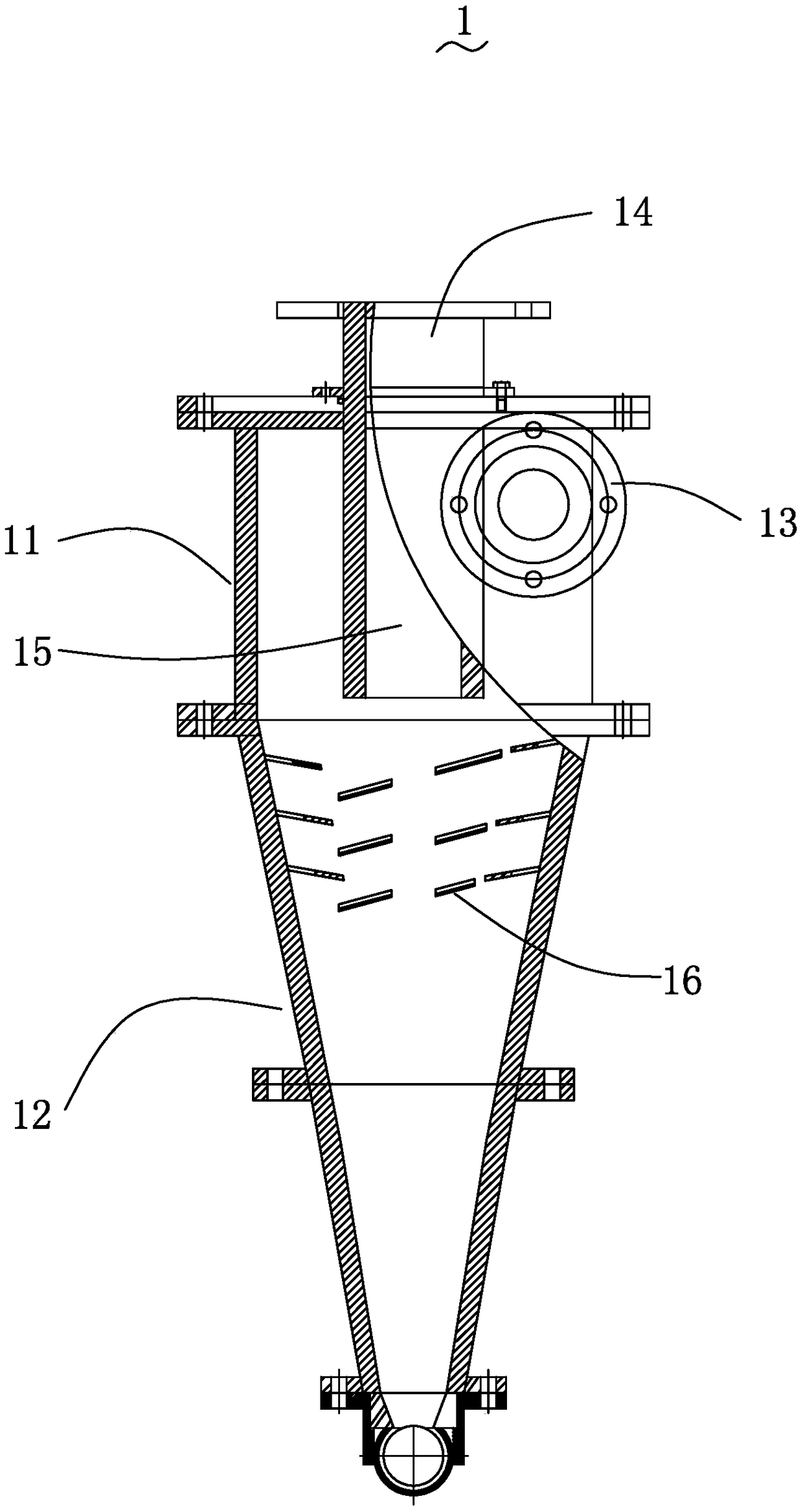
[0033] see figure 1 , is a schematic structural view of the slurry clarification device provided by the present invention. The slurry clarification device 100 of the present invention includes a primary cla...


PUM

PropertyMeasurementUnit
angleaaaaaaaaaa
pore sizeaaaaaaaaaa

Abstract

The invention discloses a slurry clarification device which comprises a primary clarification tank, a secondary clarification tank and a spiral conveyer, wherein the primary clarification tank and thesecondary clarification tank are communicated with each other, and the spiral conveyer is used for containing material residues; the primary clarification tank comprises a first straight barrel section, a first conical barrel section, a feeding opening, an overflowing opening, an overflowing pipe and a partition plate; the first conical barrel section is connected with the bottom of the first straight barrel section, the feeding opening and the overflowing opening are arranged on the first straight barrel section, the overflowing pipe is inserted into the first straight barrel section and iscommunicated with the overflowing opening, the partition plate is arranged in the first conical barrel section, the partition plate and an inner wall of the first conical barrel section are arranged at interval, and the partition plate is in a spiral shape; the secondary clarification tank comprises a second straight barrel section, a second conical barrel section, a liquid inlet pipe, a liquid outlet and a plurality of baffle plates; the second conical barrel section is connected with the bottom of the second straight barrel section, the liquid inlet pipe is communicated with the overflowingopening, is arranged along an inner wall of the second straight barrel section and extends to the second conical barrel section, the liquid outlet is arranged on the second straight barrel section, and the plurality of the baffle plates are arranged on the second conical barrel section. The slurry clarification device disclosed by the invention has high clarification efficiency and is also suitable for slurry with a slow sedimentation speed and small grain composition.

Description

technical field [0001] The invention relates to the technical field of slurry clarification, in particular to a slurry clarification device. Background technique [0002] When the slurry is washed, the washing water contains a large amount of slag. In industrial production, it is necessary to separate the washing water from liquid to solid, so that the separated washing water can be recycled. [0003] At present, the natural sedimentation method is mainly used for the liquid-solid separation of slurry. The natural sedimentation process requires a long period of standing, especially for the slurry with a small particle size distribution, the sedimentation speed is slow, a large slurry tank is required, and the production efficiency is low. [0004] In view of this, it is necessary to provide a new slurry clarification process to solve the above technical problems. Contents of the invention [0005] The technical problem to be solved by the present invention is to provide a...

Claims


Application Information

Patent Timeline
Patent Type & Authority Applications(China)
IPC IPC(8): B01D36/04
CPCB01D36/04
Inventor 蔡雪飞廖文革
Owner 湖南昌迅科技环保股份有限公司
Why Eureka
Try Eureka