Electromagnetic ball mill

A ball mill and electromagnetic technology, used in grain processing and other directions, can solve the problems of small impact force and poor grinding effect, and achieve the requirements of reducing the rotation speed and improving the grinding effect.

Active Publication Date: 2019-03-22
CHONGQING DULIANG IND CO LTD
View PDF10 Cites 5 Cited by
  • Summary
  • Abstract
  • Description
  • Claims
  • Application Information

AI Technical Summary

Problems solved by technology

[0003] Existing ball mills have high requirements on the motor speed. If the speed is too high, the grinding body will always cling to the inner wall of the cylinder and cannot fall d

Method used


Image

  • Electromagnetic ball mill
  • Electromagnetic ball mill
  • Electromagnetic ball mill

Examples


Example Embodiment

[0020] The embodiments of the technical solution of the present invention will be described in detail below in conjunction with the accompanying drawings. The following embodiments are only used to illustrate the technical solutions of the present invention more clearly, and therefore are only used as examples, and cannot be used to limit the protection scope of the present invention.
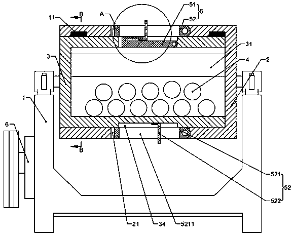
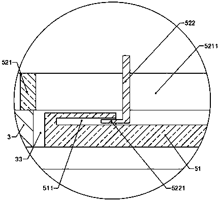
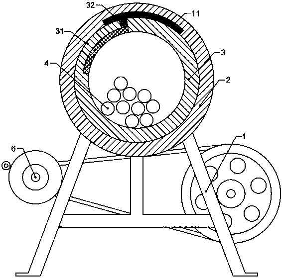
[0021] See Figure 1-4 , The electromagnetic ball mill provided in this embodiment includes a support 1, a transmission part, a cylinder 2, a cylindrical grinding container 3, and a magnetic grinding body 4; the cylinder 2 is fixed on the support 1; Two arc-shaped conductive belts 11 are installed on the top of the inner side wall of the cylinder body 1; the outer side of the cylinder body 1 is provided with a power connection port communicating with the conductive belt 11; one end of the milling container 3 is inserted into the cylinder body 2. The inner side is rotatably connected with the cyli...


PUM


Abstract

The invention provides an electromagnetic ball mill. The electromagnetic ball mill comprises a bracket, a driving part, a cylinder body, a cylindrical grinding container and magnetic grinding bodies.The cylinder body is fixed to the bracket. Two arc-shaped electric conductive strips are arranged on the top of the inner sidewall of the cylinder body. The outer side of the cylinder body is providedwith a power connector communicating with the electric conductive strips. One end of the grinding container is inserted into the cylinder body to be rotatably connected with the cylinder body, and the other end of the grinding container is rotatably connected with the bracket. An electromagnet is mounted on the inner sidewall of the grinding container. The peripheral surface of the grinding container is provided with two conductive contacts corresponding to the electromagnetic conductive strips. One end of each conductive contact abuts against the inner sidewall of the cylinder body, and theother end of each conductive contact is electrically connected with the electromagnet. The grinding bodies are placed in the grinding container. The electromagnetic ball mill reduces the requirementsfor the rotating speed and can raise the grinding bodies to the highest point conveniently and improve the grinding effect.

Description

technical field [0001] The invention relates to the field of grinding equipment, in particular to an electromagnetic ball mill. Background technique [0002] The working principle of the ball mill: the grinding body and materials are added into the barrel of the ball mill according to a certain proportion and sealed. The cylinder of the ball mill rotates under the drive of the motor, and the grinding body is attached to the inner wall of the cylinder under the centrifugal force, and rotates together with the cylinder to rise to a certain height, and is thrown down due to the action of gravity, causing the material to be impacted and ground. And was crushed. [0003] Existing ball mills have high requirements on the motor speed. If the speed is too high, the grinding body will always cling to the inner wall of the cylinder and cannot fall down; if the speed is too small, the grinding body will be thrown out due to gravity before it reaches the highest point of the cylinder. ...

Claims


Application Information

Patent Timeline
IPC IPC(8): B02C17/10B02C17/18B02C17/20B02C23/02
CPCB02C17/10B02C17/18B02C17/182B02C17/183B02C17/20
Inventor 高峰尹有木曾涛罗友玲
Owner CHONGQING DULIANG IND CO LTD
Why Eureka
Try Eureka