
Floating mechanism and battery replacement trolley including it

A floating mechanism, electric car technology, applied in the field of charging and swapping, can solve the problems of non-parallel surface and body bottom of the battery swap car, cumbersome adjustment process, low power swap efficiency, etc. Effect

Active Publication Date: 2021-12-28
NIO ANHUI HLDG CO LTD
View PDF10 Cites 0 Cited by
  • Summary
  • Abstract
  • Description
  • Claims
  • Application Information

AI Technical Summary

Problems solved by technology

[0003] Existing battery-swapping trolleys usually use positioning pins to align with the positioning holes of the vehicle body to align the battery. However, due to various factors such as vehicle lifting and uneven ground where the battery-swapping trolley is located, the surface of the battery-swapping trolley and the bottom of the vehicle body will be inconsistent. Parallel, it is usually necessary to adjust the surface of the battery swap trolley or adjust the plane of the bottom of the vehicle body so that the two are in a parallel state, so as to ensure the smooth progress of the battery swap process, the adjustment process is cumbersome, the battery swap efficiency is low, and the user experience is poor

Method used


Image

  • Floating mechanism and battery replacement trolley including it
  • Floating mechanism and battery replacement trolley including it
  • Floating mechanism and battery replacement trolley including it

Examples


Embodiment Construction

[0048] In order to further explain the technical means and effects of the present invention to achieve the intended purpose of the invention, the specific implementation of the floating mechanism proposed according to the present invention and the battery-swapping trolley including it and its Efficacy, detailed as follows.

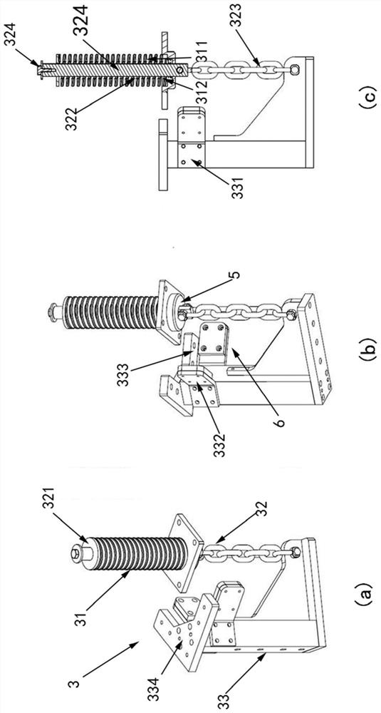
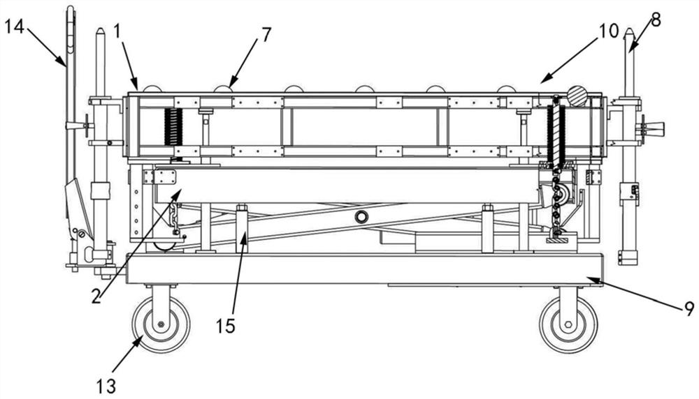
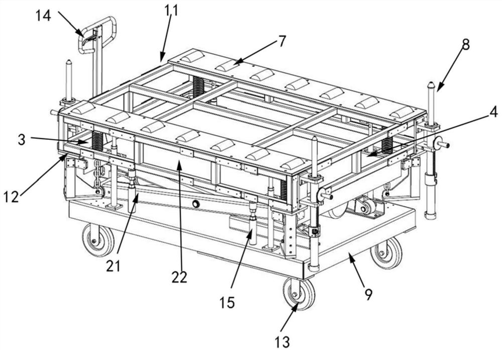
[0049] The embodiment of the present invention provides a floating mechanism, including a floating part 1, a fixed part 2 and a plurality of connecting parts 3, wherein the floating part 1 and the fixed part 2 are arranged face to face, and there is a The first floating gap 4, the floating part 1 is used to support the target object, the target object is the object to be aligned or positioned, for example, when the floating mechanism is applied to the power exchange equipment in the power exchange station, such as power exchange In the case of a trolley, the target object is a battery pack. like figure 1 (a), figure 1 (b), figure 1In the example shown ...


PUM


Abstract

The present invention relates to a floating mechanism and a battery exchange trolley including the same. The floating mechanism includes a floating part, a fixed part and a plurality of connecting parts. The floating part and the fixed part are arranged face to face with a first floating gap between them; Connecting piece, floating connecting piece and fixed connecting piece, the elastic connecting piece is arranged in the first floating gap, one end is connected with the floating connecting piece, and the other end is connected with the fixed part, the elastic connecting piece is provided with a first through hole, and the fixed part is provided with The second through hole; one end of the floating connector connected to the elastic connector is connected to the floating part, and the other end passes through the two through holes and extends outward to one end of the fixed connector. The second floating gap; the other end of the fixed connection part is connected to the floating part, and a third floating gap is provided between the fixed connection part and the fixed part. The invention can self-adaptively adjust the surface of the battery swap trolley to be parallel to the bottom of the vehicle body during the battery swap process, thereby improving the battery swap efficiency.

Description

technical field [0001] The invention relates to the technical field of battery charging and swapping, in particular to a floating mechanism and a battery swapping trolley including the floating mechanism. Background technique [0002] With the continuous development of electric vehicles, how to provide electric energy supply for electric vehicles with insufficient power in a timely and effective manner has become a problem that manufacturers and car owners are very concerned about. By lifting the vehicle and pushing the battery replacement trolley under the vehicle, the method of removing and installing the battery pack for the vehicle is a very efficient way of supplementing electric energy. During the process of replacing the battery of the vehicle, the battery replacement trolley needs to align the battery and keep it parallel to the bottom of the vehicle body. [0003] Existing battery-swapping trolleys usually use positioning pins to align with the positioning holes of...

Claims


Application Information

Patent Timeline
Patent Type & Authority Patents(China)
IPC IPC(8): B60L53/80B62B3/02
CPCB62B3/02B60S5/06B62B2202/61Y02T10/70Y02T10/7072
Inventor 丁习坤林海岩李楠田小涛刘俊马永跃
Owner NIO ANHUI HLDG CO LTD
Learn More