Soluble bridge plug

A bridge plug and mandrel technology, applied in the field of soluble bridge plugs, can solve the problems of high risk of encountering obstacles and single direction of the bridge plug slip teeth, and achieve the effects of reducing potential safety hazards, reducing area and reducing damage

Inactive Publication Date: 2019-03-22
成都铭鉴知源油田工程科技有限公司 +1
View PDF7 Cites 5 Cited by
  • Summary
  • Abstract
  • Description
  • Claims
  • Application Information

AI Technical Summary

Problems solved by technology

[0004] The purpose of the present invention is: in order to solve the problem that the existing bridge plug has a single slip tooth direction during the setting process, resulting in a high risk of downhole obstruction, the present invention provides a soluble bridge plug

Method used


Image

  • Soluble bridge plug
  • Soluble bridge plug

Examples


Embodiment 1

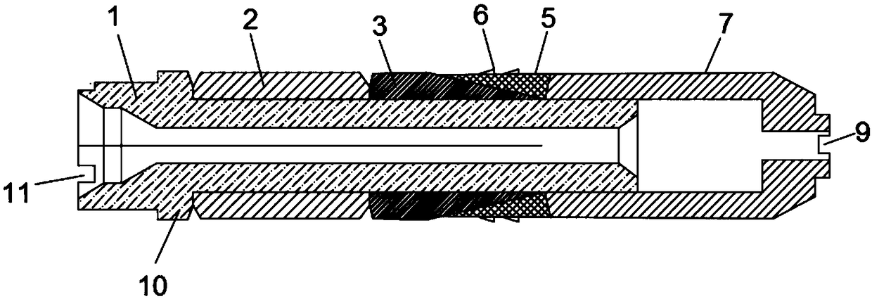
[0028] Such as Figures 1 to 2 As shown, this embodiment provides a dissolvable bridge plug, including a mandrel 1, a rubber sleeve 2, a cone sleeve 3, slips 5 and a lower joint pup 7; the mandrel 1 is a hollow structure, and the The mandrel 1 is provided with a limiting boss 10, and the rubber sleeve 2 and the cone sleeve 3 are sequentially sleeved on the outer surface of the mandrel 1 on one side of the limiting boss 10; The boss 10 is in contact with each other, and the other end of the rubber sleeve 2 is in contact with the end away from the tapered surface of the cone sleeve 3; there are multiple slips 5, and the cone sleeve 3 is provided with the number of slips 5 Corresponding to the guide groove 4, the plurality of slips 5 are located on the tapered surface of the cone sleeve 3 through the radial limit structure; one end of the lower joint nipple 7 is slidably sleeved on the other end of the mandrel 1 And abut against the slips 5, the other end of the lower joint nipp...

Embodiment 2

[0030] Such as Figures 1 to 2 As shown, this embodiment has been further improved on the basis of embodiment 1. Specifically, the rubber cylinder 2 is a single rubber, and the existing rubber cylinder adopts double rubber. If there is no pumping in place, the upper and lower rubber of the double rubber is easy to crack Opening causes the setting seal to not be in place, and the present invention avoids the above-mentioned risks by adopting a single rubber.

[0031] The mandrel 1, the rubber tube 2, the cone sleeve 3, the slips 5 and the lower joint sub-joint 7 are all made of soluble materials.

Embodiment 3

[0033] Such as Figures 1 to 2 As shown, this embodiment is further improved on the basis of embodiment 2. Specifically, the end of the mandrel 1 away from the lower sub-section 7 is provided with a plurality of grooves-11, which can reduce the dissolution time of the bridge plug. A plurality of grooves 2 8 are arranged on the lower joint sub-section 7 to reduce the dissolving time of the bridge plug to meet the working time requirement. The second groove 8 is a strip groove. The depth of the second groove 8 is 3-6mm.

[0034] When the temperature is 90°C, the pressure is 70MPa, and the chloride ion concentration is 10000mg / L, the dissolution time of Example 2 of the present invention is 240h, and the dissolution time of Example 3 of the present invention is 180h, indicating that the mandrel 1 is far away from the lower joint. One end of section 7 is provided with a plurality of grooves 11 and a plurality of grooves 2 8 are arranged on the lower joint sub-section 7, which ca...


PUM


Abstract

The invention discloses a soluble bridge plug and relates to the technical field of downhole tools of oil and gas wells. The problem is solved that the slip tooth direction is simple in the setting-packing process of an existing bridge plug and accordingly the underground resistance risk is high. The soluble bridge plug comprises a mandrel, a rubber cylinder, a cone sleeve, multiple slips and a lower joint short section, wherein the mandrel is of a hollow structure and is provided with a limiting boss, the rubber cylinder and the cone sleeve sequentially and slidingly sleeve the outer surfaceof the mandrel on one side of a limiting boss, the multiple slips are located on the conical face of the cone sleeve through a radial limiting structure, one end of the lower joint short section slidingly sleeves the other end of the mandrel and abuts against the slips, each slip is provided with multiple slip teeth, the slip teeth are oblique truncated cylinders and include lower slip teeth downward inclining in the oblique cross section direction as the conical surface directions of the cone sleeve and upper slip teeth upward inclining in the oblique cross section direction as the conical surface directions of the cone sleeve. The downhole resistance risk is reduced, and the potential safety hazards of oil and gas well operation are reduced.

Description

technical field [0001] The invention relates to the technical field of downhole tools for oil and gas wells, and more particularly relates to a soluble bridge plug for isolating wellbore pressure in a wellbore. Background technique [0002] The existing soluble bridge plugs are mainly made of soluble metals after special treatment. After the operation is completed, they can be completely dissolved in the downhole liquid environment and flow back to the surface, with zero residue downhole; eliminating the need for later drilling and grinding bridge plugs time, reduce possible risks, and realize early production of oil and gas wells. The fully soluble bridge plug can be set with conventional setting tools, such as Baker No. 20 setting tool, etc. After the bridge plug is set and perforated, dissolvable fracturing balls are put into the stage to start fracturing the stage. In the later dissolution process, the dissolution time of the fully soluble bridge plug can be customized ...

Claims


Application Information

Patent Timeline
Patent Type & Authority Applications(China)
IPC IPC(8): E21B33/134E21B23/01
CPCE21B23/01E21B33/134
Inventor 张珂涵缪云张德兰洪玉奎李蕾覃芳冯星铮
Owner 成都铭鉴知源油田工程科技有限公司
Why Eureka
Try Eureka