

Stopping block for inertial sensor
An inertial sensor and blocking block technology, applied in the MEMS field, can solve problems such as easy adhesion, charge accumulation, and easy damage, and achieve the effects of increasing firmness, reducing the possibility of damage, and increasing the effective contact area
- Summary
- Abstract
- Description
- Claims
- Application Information
AI Technical Summary
Problems solved by technology
Method used
Image

Examples
Embodiment Construction
[0015] The specific implementation of the blocking block for the inertial sensor provided by the present invention will be described in detail below with reference to the accompanying drawings.
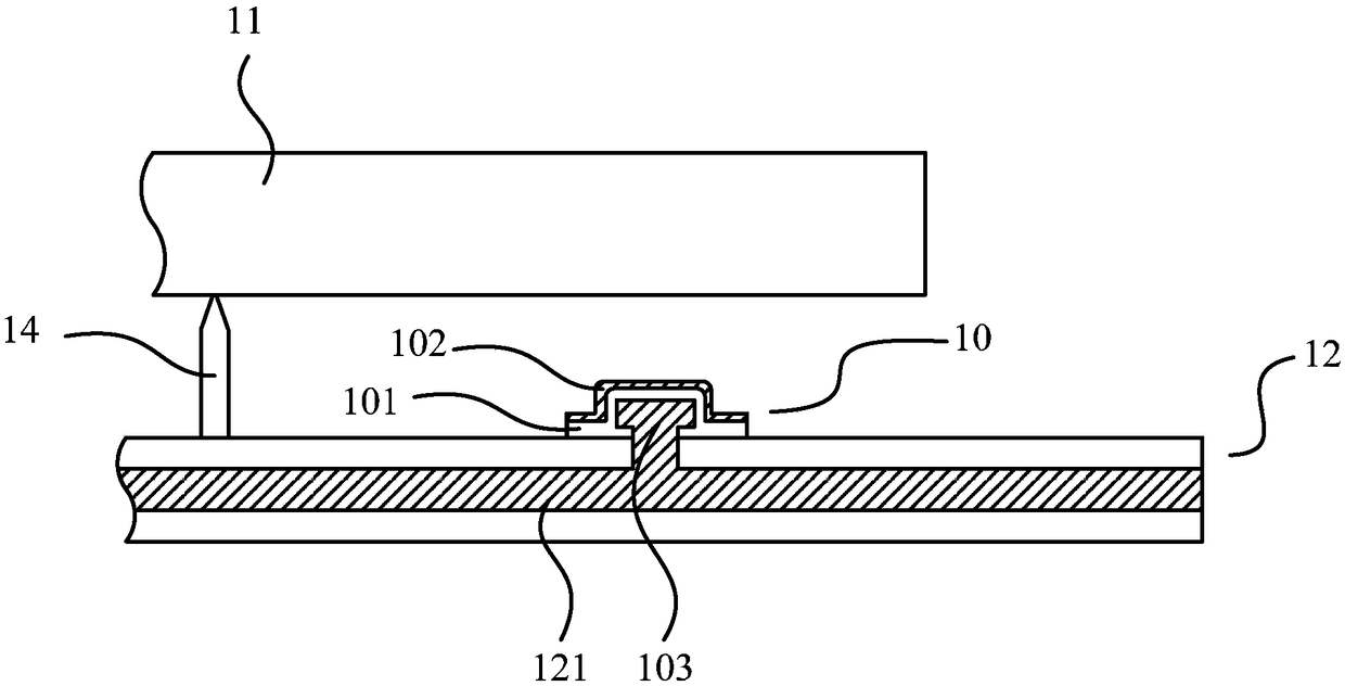
[0016] attached figure 1 Shown is a partial structural schematic diagram of the inertial sensor described in this specific embodiment, including a blocking block 10 , a mass block 11 , and a base 12 . The blocking block 10 includes a body 101 , a covering layer 102 and a conductor 103 .
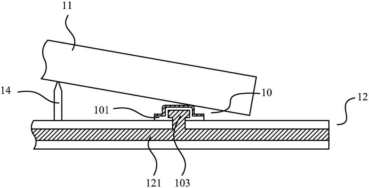
[0017] attached figure 2 shown is attached figure 1 The state diagram of the structure of the mass block 11 is displaced around the anchor point 14 and is in contact with the blocking block 10 . It can be seen from the figure that the contact position between the body 101 and the mass block 11 is rounded, which can increase the effective contact area between the body 101 and the mass block 11, and reduce the possibility of damage to the blocking block after being hit. sex. Moreover, the surface...
PUM
 Abstract
Description
Claims
Application Information