Supercharge Your Innovation With Domain-Expert AI Agents!

Automatic centrifugal pretreatment device for water quality detection

A pretreatment device and automatic centrifugation technology, applied in the preparation of test samples, etc., can solve problems such as lack and reduce water sample turbidity, and achieve the effects of short time-consuming period, improved detection accuracy, and improved early warning efficiency

Pending Publication Date: 2019-03-22
HANGZHOU WEIZHIZHAO INTELLIGENT TECH CO LTD +1
View PDF0 Cites 1 Cited by
  • Summary
  • Abstract
  • Description
  • Claims
  • Application Information

AI Technical Summary

Problems solved by technology

Therefore, there is a lack of a pretreatment device that can quickly reduce

Method used


Image

  • Automatic centrifugal pretreatment device for water quality detection
  • Automatic centrifugal pretreatment device for water quality detection
  • Automatic centrifugal pretreatment device for water quality detection

Examples


Embodiment 1

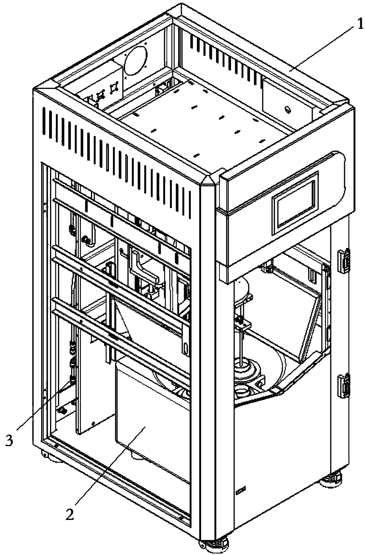
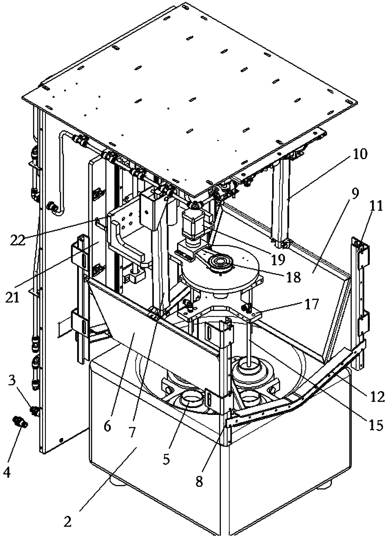
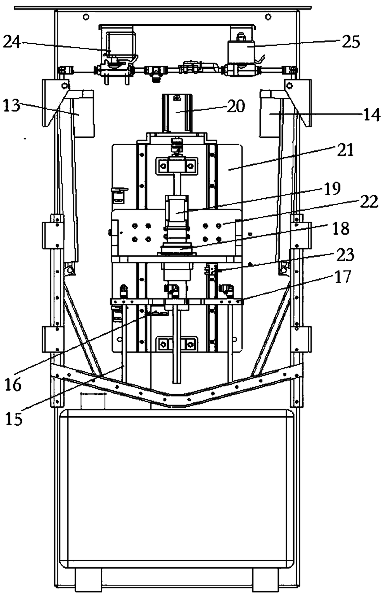
[0034] Such as figure 1 , 2 , 3 and 6, an automatic centrifugal pretreatment device for water quality detection, including a casing 1, a centrifuge 2, a water inlet pipe 3, a water outlet pipe 4, a centrifugal cup 5, a left cover door 6, a left power rod 7, a left Chute 8, right cover door 9, right power rod 10, right chute 11, down chute 12, left cylinder 13, right cylinder 14, connecting pipe 15, position sensor 16, rotating plate 17, pulley 18, rotating machine 19. Elevator 20, fixed plate 21, lifting plate 22, height sensor 23, water outlet pump 24 and water inlet pump 25, inside the shell 1, the water inlet pipe 3, the water outlet pipe 4, the left power rod 7, the left chute 8, The right cover door 9, the right power rod 10, the right chute 11, the left cylinder 13, the right cylinder 14 and the fixed plate 21, the water inlet pipe 3 communicates with the water inlet pump 25 through the pipeline, and the water inlet pump 25 passes through the water inlet of the connecti...

Embodiment 2

[0037] This embodiment is basically the same as Embodiment 1, the difference is: as figure 1 , 4 , shown in 6, in embodiment 2, cancel left power bar 7, left chute 8, right power bar 10, right chute 11, down chute 12, left cylinder 13 and right cylinder 14, be fixed on shell 1 bottom instead Left rotary motor 26 and right rotary motor 27 at two ends, left rotary motor 26, right rotary motor 27 are connected with left cover door 6, right cover door 9 by rotating shaft, during work, left rotary motor 26 and right rotary motor 27 are driven by rotation The left cover door 6 and the right cover door 9 rotate.

Embodiment 3

[0039] This embodiment is basically the same as Embodiment 1, the difference is: as figure 1 , 5 , shown in 6, in embodiment 2, cancel left power bar 7, left chute 8, right power bar 10, right chute 11, down chute 12, left cylinder 13 and right cylinder 14, be fixed on shell 1 bottom instead Rotating motor 28 and chute 29, rotating motor 28 is connected with left cover door 6 by rotating shaft, and left cover door 6 is connected with right cover door 9 by rotating shaft, and right cover door 9 other ends are connected chute 29 by pulley, during work, The rotation of the rotating motor 28 drives the left cover door 6 to rotate and then the right cover door 9 moves linearly along the chute 29 .


PUM


Abstract

The invention discloses an automatic centrifugal pretreatment device for water quality detection. The device comprises a casing, a water inlet member, a water outlet member, a slewing mechanism, a centrifugal mechanism, a controller and pipelines, wherein the water inlet member, the water outlet member, the slewing mechanism and the centrifugal mechanism are fixedly connected with the casing; thewater inlet member communicates with the slewing mechanism through a pipeline; the slewing mechanism communicates with the water outlet member through the pipeline; the slewing mechanism is matched with the centrifugal mechanism; the slewing mechanism comprises a lifting member, a rotating member, a position sensing member and connecting pipes; the lifting member is fixedly connected with the rotating member; the rotating member is connected with the position sensing member; the connecting pipes communicate with the pipelines; the centrifugal mechanism comprises a centrifuge, a power member, cover doors and centrifugal cups; the centrifugal cups are fixed inside the centrifuge; a position sensor is matched with the centrifugal cups; the connecting pipes are matched with the centrifugal cups; the power member is fixedly connected with the casing; and the power member is connected with the cover doors.

Description

technical field [0001] The invention belongs to the field of water quality detection instruments, in particular to an automatic centrifugal pretreatment device for water quality detection. Background technique [0002] The mainstream brand of total phosphorus automatic monitoring instrument used by the automatic water quality monitoring station generally adopts the ammonium molybdate spectrophotometric method for the analysis principle, which is consistent with the manual monitoring method, but there are certain differences between the digestion process and the water sample pretreatment process and the laboratory method . The difference in the process leads to the difference in the test results, especially when the turbidity in the water is high, the automatic monitoring results of parameters such as total phosphorus will be obviously interfered by the turbidity, and generally have a positive correlation. Therefore, there is a lack of a pretreatment device that can quickly ...

Claims


Application Information

Patent Timeline
IPC IPC(8): G01N1/28
CPCG01N1/28
Inventor 王静雷冯元群姚德飞王国胜张丹腾曼赵岑杨婧刘立丽
Owner HANGZHOU WEIZHIZHAO INTELLIGENT TECH CO LTD
Features
  • R&D
  • Intellectual Property
  • Life Sciences
  • Materials
  • Tech Scout
  • Unparalleled Data Quality
  • Higher Quality Content
  • 60% Fewer Hallucinations
Learn More